The complete reference, readable in your browser. Choose a chapter or use your browser’s Find command to search.
This edition preserves the original manual, including older HMI Pad names, screenshots, and service references. For current support, contact RiteControl.
The HMI Editor app is the developer component of the HMI Pad system
for creating Human Machine Interfaces for real time monitoring of
industrial PLC based systems and processes. The other two components are
the HMI app and the HMI Pad Service.
Main features.
Very fast native app, launches and connects immediately
regardless of project size, not a web based app.
All data types supported including Boolean, Integer and Floating
Point values.
Advanced Expressions Engine supporting a number of data types
including Strings, Arrays and Dictionaries.
Projects can be fully edited on-screen as you run and monitor
your process. Or can be exported and edited as a text file.
Configurable User Accounts allow for project storage in the cloud
and easy deployment to end users.
The app connects to PLCs directly using native communication
protocols. Connections are performed without any intermediate servers or
boxes.
TCP/IP based security.
The concept behind the HMI Pad apps.
The HMI Editor and HMI apps are built on top of two main modules: the
Communications Module and the Expressions Engine.
These modules interact with each other and to the user interface to
provide most of the underlying capabilities and many advanced
features.
The HMI Editor lets Integrators build fully
customizable HMI interfaces by adding visual items or other objects to
pages. Objects have properties that can be connected between them or
with PLC tags through expressions. Virtually all properties can be
linked through expressions. This architecture provides an extremely
powerful environment for Integrators to create advanced HMI
interfaces.
HMIs can be fully created and deployed from the app by dragging and
connecting items together. Integrators can also chose to edit project
files on a text editor. The app also fully supports copy/paste/duplicate
of items, tags, connections etc, and has unlimited undo/redo
capabilities.
The app comes with a free service on the cloud, the HMI Pad
Service, for convenient storage of projects and associated
assets and further deployment to End Users.
The complementary HMI app let automation integrators
to safely and securely deploy projects to end users devices with no
physical access to them. Projects on the HMI app are installed as
encrypted, non-editable instances of your projects, thus helping you to
safely keep your work and know how.
1 The HMI Pad System Components
The HMI Pad System is made up of 3 components:
HMI Editor.
This the app Integrators use to create and deploy HMI projects.
HMI Pad Service.
The HMI Pad app is designed to work with a service in the cloud named
the HMI Pad Service.
The app seamlessly integrates this service to provide storage options
in the cloud and convenient distribution and deployment of your HMI
projects to your End Users or customers. The HMI Pad Service uses
Apple's CloudKit infrastructure as the physical media to store data in
the cloud.
Refer to the "HMI Pad Deployment Guide" for
more information on what options you have available to work with the HMI
Pad Service as you develop HMI projects.
HMI Pad View.
This is the app where end users run HMI projects developed by
integrators. Projects on the HMI app are installed through the HMI Pad
Service and are stored as encrypted instances that can not be edited or
moved to other devices.
2 The HMI Editor app main user Interface
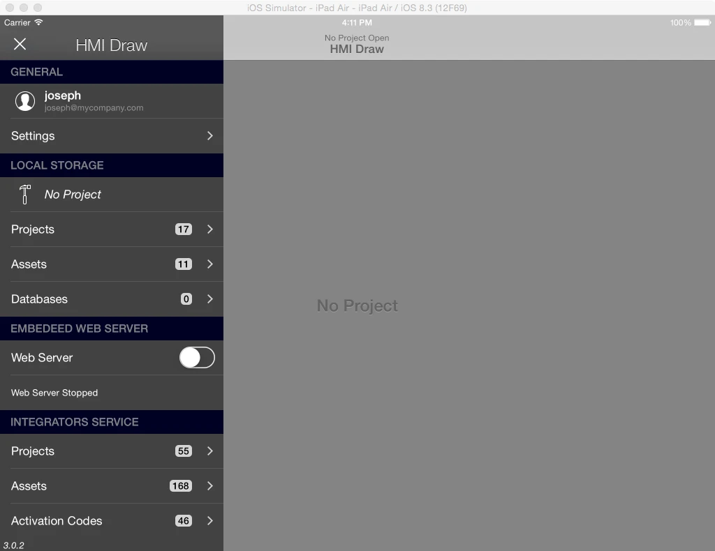
The HMI Editor app interface consists of two main draggable panels,
the Application Panel and the Project Viewer.
The Application Panel is shown on the left and there you will find
options and settings related with the app.
The Project Viewer is on the right and lets you edit, review and run
your project. The Project Viewer can be made full screen by closing the
Application Panel.
2.1 The Application Panel
The Application Panel lets you create and manage the following
aspects of the app
User Accounts and Settings.
Projects and Assets stored locally.
Projects and Assets stored on the HMI Pad Service
Remote Deployment.
2.1.1 Settings
The Settings panel is reached from the GENERAL
section of the Application Panel sidebar. It groups app-wide
preferences, maintenance actions, and links to documentation. Changes
take effect immediately and are persisted across launches.
Alarms and Background Task
Disable Auto-Lock. When enabled, prevents iOS
from putting the device to sleep while HMI is in the foreground — useful
for kiosk or always-on installations. Disabled (greyed out) on Mac
Catalyst, where the system idle timer is not affected by the
app.
Haptic Feedback / Pulse
Feedback. Provides physical feedback when interacting with
controls (Button, Switch, Custom Switch, Slider, Knob, Segmented
Control, Array Picker, Dictionary Picker, Tap Recognizer). On devices
with a Taptic Engine the row is labelled Haptic Feedback and
uses the standard iOS impact / selection generators. On older iPhone,
iPad and Mac Catalyst hardware the row is labelled Pulse
Feedback and uses a short system click sound as a fallback. Enabled
by default.
Alarm on Disconnection. When enabled, raises an
alarm event if a PLC, REST, or MQTT connector loses its
connection.
Keep Connected. When enabled, HMI Editor keeps
PLC, REST and MQTT connections alive while you switch to another app.
When disabled, connections are torn down when HMI goes to the background
and re-established on return.
Maintenance
Clear Image Cache. Empties the on-device image
cache. Use it if an image is not updating after being renamed or
replaced.
Delete Pending Receipts. Clears any pending
in-app-purchase receipts that were not consumed.
Embedded Web Server
Port. TCP port used by the embedded Web Server
(default 8080). Change it if another app on the device is using the same
port.
Give Feedback / Help
Quick links to the App Store review page, this Reference Manual, the
Deployment Guide, and Technical Support.
2.2 The Project Viewer
The Project Viewer is where you create, configure, edit and run
projects. From the Project Viewer you get access to Pages, Connections,
Alarms and the internal aspects of your project. You can also set some
editing properties and edit objects on screen using common gestures.
Several sub-panels provide means to navigate through your project to
obtain detailed information. You may find the following panels that will
appear at appropriate times or upon particular actions as you edit your
project:
Page Viewer, shows the current page. The
Page Navigator appears from the left and displays the
list of pages.
Inspector Panel, appears from the right and
contains the Connections Panel, the Tag Viewer and the
Alarms Viewer.
Model Browser, appears as a floating window you
can drag around the screen.
Object Configurator, appears as a floating
window when you tap on 'configure' for an object.
Expressions Keyboard, appears on the bottom of
the screen, when editing Object Properties.
PLCs and TAGs Configuration Panels, appear as
floating windows, accessible from the Model Browser
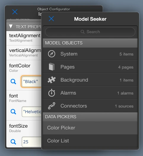
Model Seeker, appears as a floating window,
accessible from the Object Configurators or the Expressions
Keyboard
2.2.1 The Model Seeker
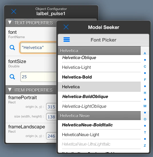
The Model Seeker is the picker that opens when you
tap the search (magnifying glass) icon next to a property field in the
Object Configurator, or the corresponding key on the Expressions
Keyboard. It lets you fill the field by selecting a value from a list
rather than typing one.
The Seeker shows different content depending on the property’s data
type:
For most expression properties it lists the project objects,
connectors, tags, and system values that can supply a value to that
property.
For image-path properties (such as a Shape’s
fillImage, an Image item’s imagePath, or a Button’s
image), the Seeker presents an SF Symbols tab
containing the full Apple SF Symbols catalogue, grouped into categories
such as Arrows, Indicators, Communication and
so on. A search bar at the top filters the grid by symbol name.
Tapping a symbol fills the property with the symbol’s identifier (for
example arrow.up or bolt.fill). SF Symbols are
rendered using the system tint and respect the current color settings of
the item — they scale cleanly at any size and adapt automatically to
light / dark appearance.
3 Creating and opening Projects
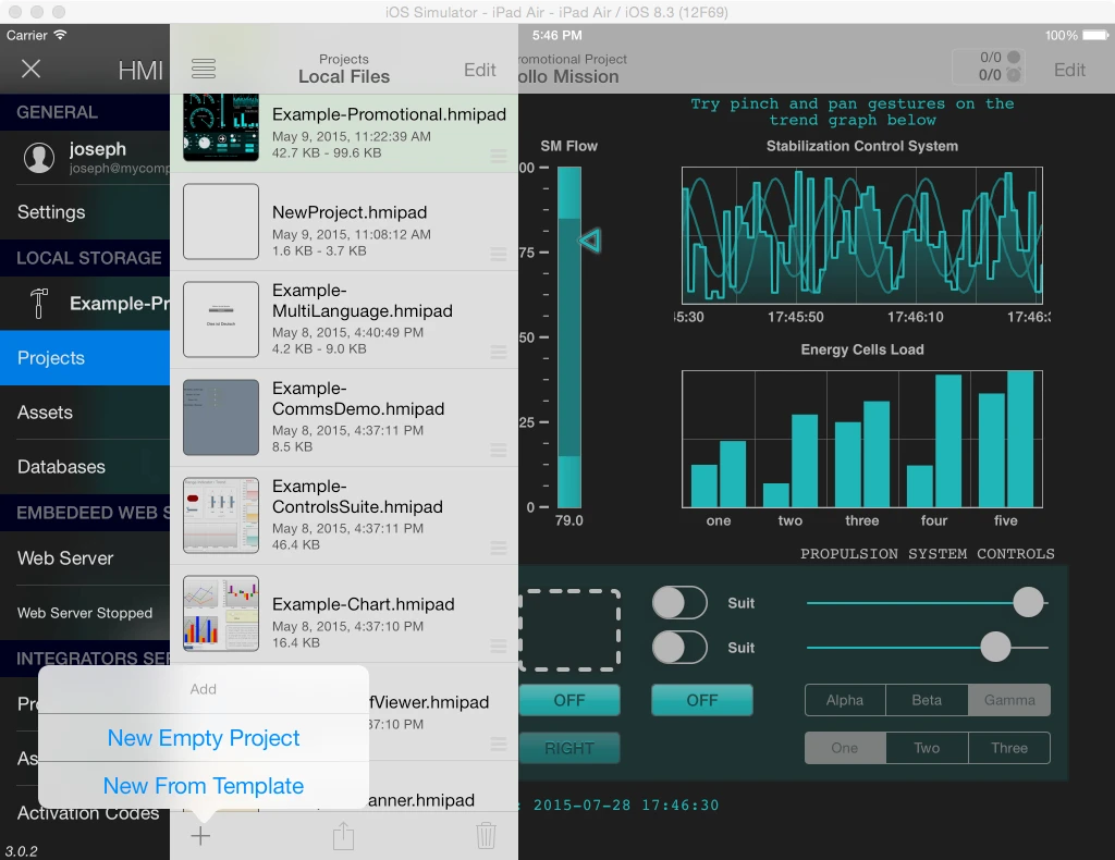
To create a new project go to "Local Storage -> Projects" on the
"Application Panel" and tap on "+", then chose "New Empty Project". A
new project with a default name will appear on the list. Alternatively,
you can tap on "New From Template" and the app will show you a list of
already made simple projects you can use to start from.
You can open the project you just created by "sliding" to the right
the row in the list containing its name.
NewProject.png
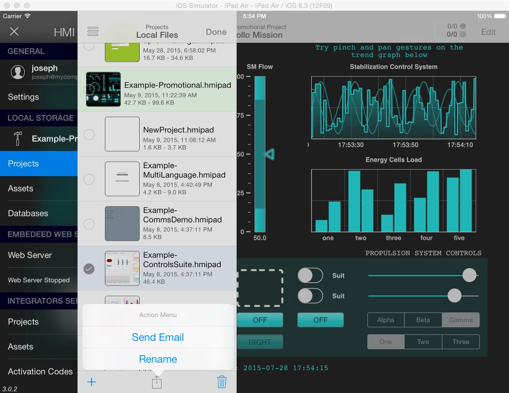
It is recommended to rename your projects with suitable names that
clearly identifies them to you. To do so set the list to edit mode by
tapping on "Edit", then select the project you want to rename, and
choose the appropriate option from the "Actions" menu on the bottom of
the panel.
RenameProject.png
3.1 The Current Project Panel
When a project is open it appears under LOCAL
STORAGE in the Application Panel sidebar. Selecting it shows a
Current Project panel with the project thumbnail, identifying metadata
(Project ID, Date, Size), and a set of per-project options.
Start Page
The Start Page selector — labelled Set the page to open when the
project starts — controls which page is shown when the project is
next opened. Tap the selector to choose one of:
Last Used — open the page that was active when
the project was last closed. This is the historical default.
Any page identifier in the project — open that page every time
the project starts, regardless of which page was active at
close.
The selection is stored per-project (keyed by the project UUID) and
survives reopening the app.
Project actions
Activate. Stores this Project in the Cloud, or
activates it for end users.
Duplicate. Creates a new local project based on
this one, preserving items, expressions, connectors and assets.
Close. Closes the project.
Test Project using its Attached Assets. When on,
the project is exercised against the assets bundled with it rather than
the ones on local storage.
The Current Project panel also lists Required Local
Assets — files referenced by the project that should be present
on the device before deployment.
4 Editing Projects in the Project Viewer
With the HMI Editor app you can fully edit your HMI projects on the
"Project Viewer". When the project viewer is fully visible tap on
the"Edit" button on the top-right of the panel to start editing your
project.
It is not a purpose of this manual to fully describe all and every
editing option available, but just to provide a guide on what is at your
disposal to complete your editing and where to look at for a specific
editing need. For the most part the app interface follows commonly
recognized patterns and provide built-in help that should be enough for
the common cases.
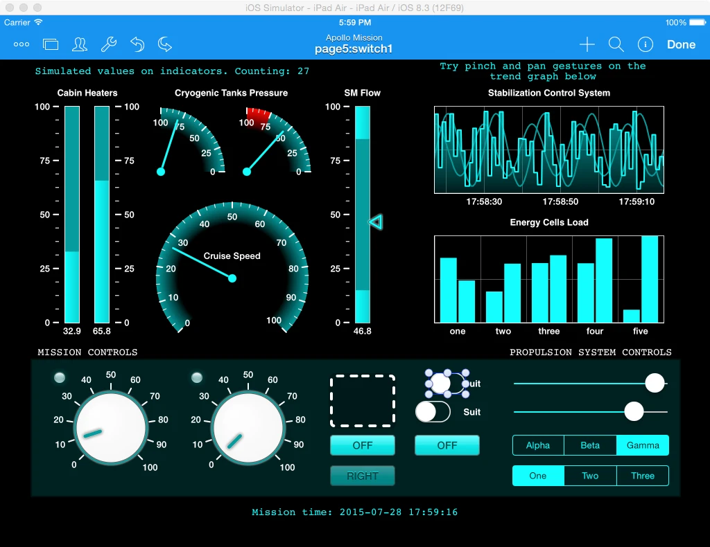
The Project Viewer features a toolbar on the top with the following
options from left to right:
Pages toolbar icon.
The pages tab bar icon toggles the Page Viewer. From
the Page Viewer you can navigate to a particular page in order to open
it. The Page Viewer can also be shown/dismissed with a drag gesture over
it or from the left edge of the Project Viewer.
User toolbar icon.
The User toolbar icon presents a project user login screen. For more
information on project users look at the $UsersManager and
Users sections in this manual.
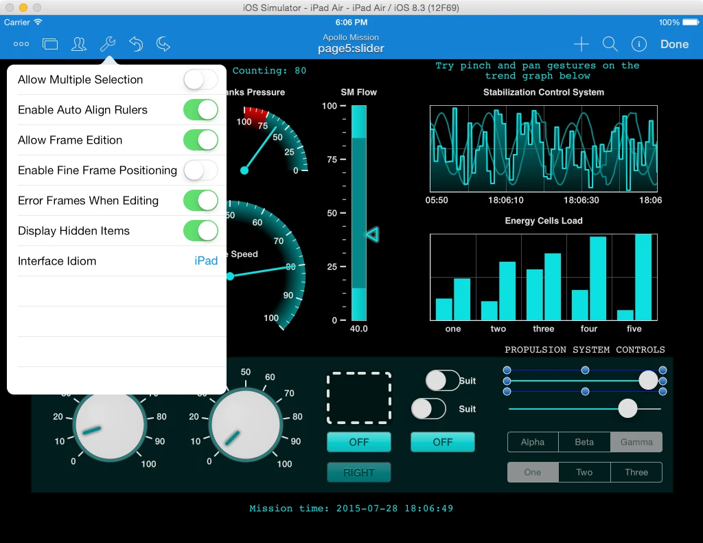
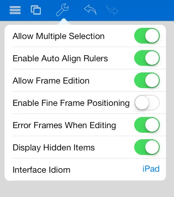
Tools toolbar icon (edit mode only).
Several tools are available for helping on positioning items on pages
and editing frames. You will find options to enable or disable auto
align rulers, to lock frame editing and to enable multiple selection.
You can also enable/disable visual reporting of error conditions while
in edit mode or make hidden items visible while in edit mode.
A number of editing tools are available:
Allow Multiple Selection. When enabled, multiple
item selection will be active, allowing for multiple selection of items
for example for grouping. Default is Off.
Enable Auto Align Rulers. Determines whether
auto-alignment rulers and alignment magnets are enabled. Switch it to
off to allow free layout of items. Default is On.
Allow Frame Editing. By setting this to off any
layout changes of items will be globally disabled. You still will be
able to set item properties. You can disable frame editing on particular
items by locking them individually. Default is On.
Enable Fine Frame Positioning. Determines whether a
joy-stick tool will appear for selected items allowing for fine
positioning and resizing of items. When arranging items using this tool,
auto-alignment rulers will still display on screen for a second but no
alignment magnets will be in effect. Default is Off.
Error Frames When Editing. Determines whether error
frames are displayed around objects with undefined values also on edit
mode. Disabling this eliminates page clutter while editing in case you
do not have a life PLC connection or your object properties contain
broken links. Default is On.
Display Hidden Items. Items with their hidden
property set to Off are still partially visible on edit mode. However
you can override this behavior by setting this to Off. Default is On
Interface Idiom. Represents the Interface Idiom you
are working on. Chose iPad for building screens for the iPad
native resolution or iPhone for working on interfaces designed
for iPhone or iPod touch.
Undo/Redo toolbar icons (edit mode only).
The app has unlimited undo-redo capabilities that are supported on
virtually all changes performed on projects.
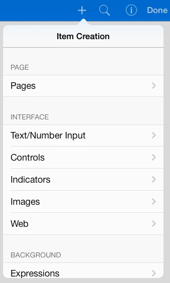
New Item toolbar icon (edit mode only).
From this toolbar icon you create new pages or new visual items that
you can place on pages or use on your HMI projects. Items are arranged
in categories such as Controls, Indicators, Images and so on. New items
are created with default properties and placed on the center of the
page, you can then move them to the desired position and configure their
properties. The application also features intelligent
copy/paste/duplicate of Objects, Pages, Connectors, Tags , including
among different projects.
Model Browser toolbar icon (edit mode only).
The model browser icon toggles the Model
Browser.
Inspector toolbar icon
The Inspector toolbar icon toggles the Inspector
Panel The Inspector Panel can also be shown/dismissed with a
drag gesture over it or from the right edge of the screen. In view mode
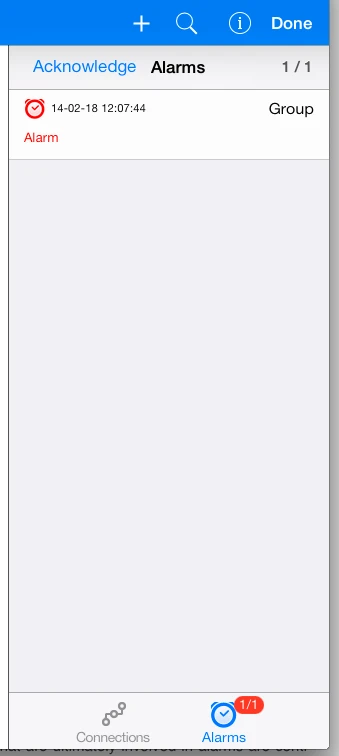
the toolbar button is replaced by a clickable area that shows the number
of active/number PLC connectors, and the number of active/total
alarms
Edit/Done toolbar icon
The Edit/Done toolbar icon toggles the project from Edit to View
mode. As a visual effect the entire toolbar becomes blue while in edit
mode.
4.1 Editing Projects in a Text Editor
Project Files in HMI Editor are plain text files that can be manually
edited on a text editor. Project Files can be exported and imported to
HMI Editor through the Mail application. They have a .hmipad extension
and HMI Editor recognizes any Mail attachment with this extension as a
HMI Editor Project File.
If you open an HMI Project file (extension .hmipad) on a text editor
you will be able to identify all the Objects and Properties of your
project as they were configured in the application. Indeed, a Project
File is a text representation of everything in a project and a direct
description of what you see on the Model Browser. This of course
includes all Visual Items on Pages, Background Items, Alarms, Connectors
and PLC Tags.
For example, a knob control on a page may look like this in the
.hmipad file
The ability to manually editing your projects using a Text Editor is
an advanced feature that you can use to create and store project
templates, quickly add/replace tags in bulk, find objects and properties
for debugging purposes, configure pages or groups of objects with
repetitive patterns, and more.
IMPORTANT NOTE: This is a very advanced feature that brings a lot of
power, but it also carries the risk of accidentally breaking Project
functionality or introducing syntax errors on Project Files that would
prevent them from being opened by HMI Editor.
HMI Editor will attempt to report syntax or other errors on imported
files in an accurate way but still you may fail at attempting to fix a
particular issue after incorrect manual editing of a file. Therefore, it
is strongly recommended to always keep a working copy of your projects
in safe place, so you can recover from them in case something goes
really wrong.
4.2 Moving Items Between Pages
Selected items on a page can be moved to another page in a single
step, rather than being copied + deleted manually. The operation is
atomic — both the removal from the source page and the insertion on the
destination page happen inside the same undo group, so one undo reverses
the entire move.
To move items between pages:
In edit mode, select one or more items on the source
page.
Long-press (or right-click on Mac) any selected item to open the
context menu. Tap MoveToPage.
The Model Browser opens at the Pages list. Tap
the destination page to open it.
Tap the action (upload) button at the bottom of
the Model Browser. A Move option now appears in the
action sheet — choose it to drop the items onto the destination
page.
If you change your mind before completing step 4, simply close the
Model Browser; the source page is left unchanged.
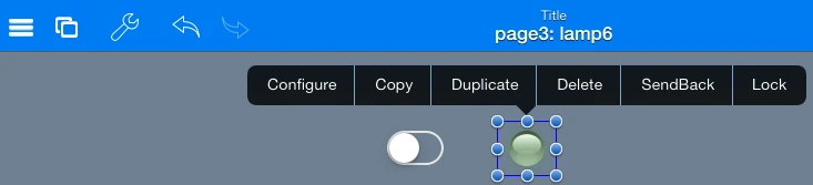
The same context menu also exposes Copy,
Duplicate, Delete,
SendBack, BringFront and
Lock for selected items.
5 Objects, Properties and the Project Object Model
As you build your HMI project you create Pages, Visual Items, PLC
connections, PLC Tags, Alarms and so on. Everything you place on pages
and the remaining objects you use to build a project are stored in the
Object Model. The Object Model also contains object configurations and
all the expressions you used to link objects.
The HMIDraw app is entirely based on Objects,
everything is achieved through connecting objects, and every aspects of
your HMI project development is based on managing objects of different
kinds.
In HMI Editor there is not a separate concept for generating displays
and constructing control logic. There are not either separate procedures
for each kind of task. Instead, you concentrate all your development on
one single easy concept. It is very likely that you already understand
the concept because it is not new to you. You already know how to link
cells on an Excel spreadsheet using formulas to produce results that
depend on other cell values, so this is it.
Objects in the HMI Editor app have Properties. Going
back to the spreadsheet analogy, object properties are the equivalent to
spreadsheet cells.
To create an HMI project with HMI Editor you simply create objects
and link their properties together using expressions, just as you would
do to link cells on a spreadsheet program. This concept extends to the
whole app and includes the way objects are linked to PLC tags.
Effectively, tags are just properties of a special kind of object called
Connector.
The Object Model is internally architected as a tree-like graph of
objects connected through expressions. When something changes at some
point of the model, for example due to an user action or a PLC tag
change, a change event is propagated only to the affected object
properties. The application is even-driven to its core, which means that
this also applies to display updating, alarming and control logic, and
it makes the app very efficient.
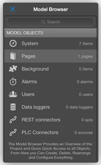
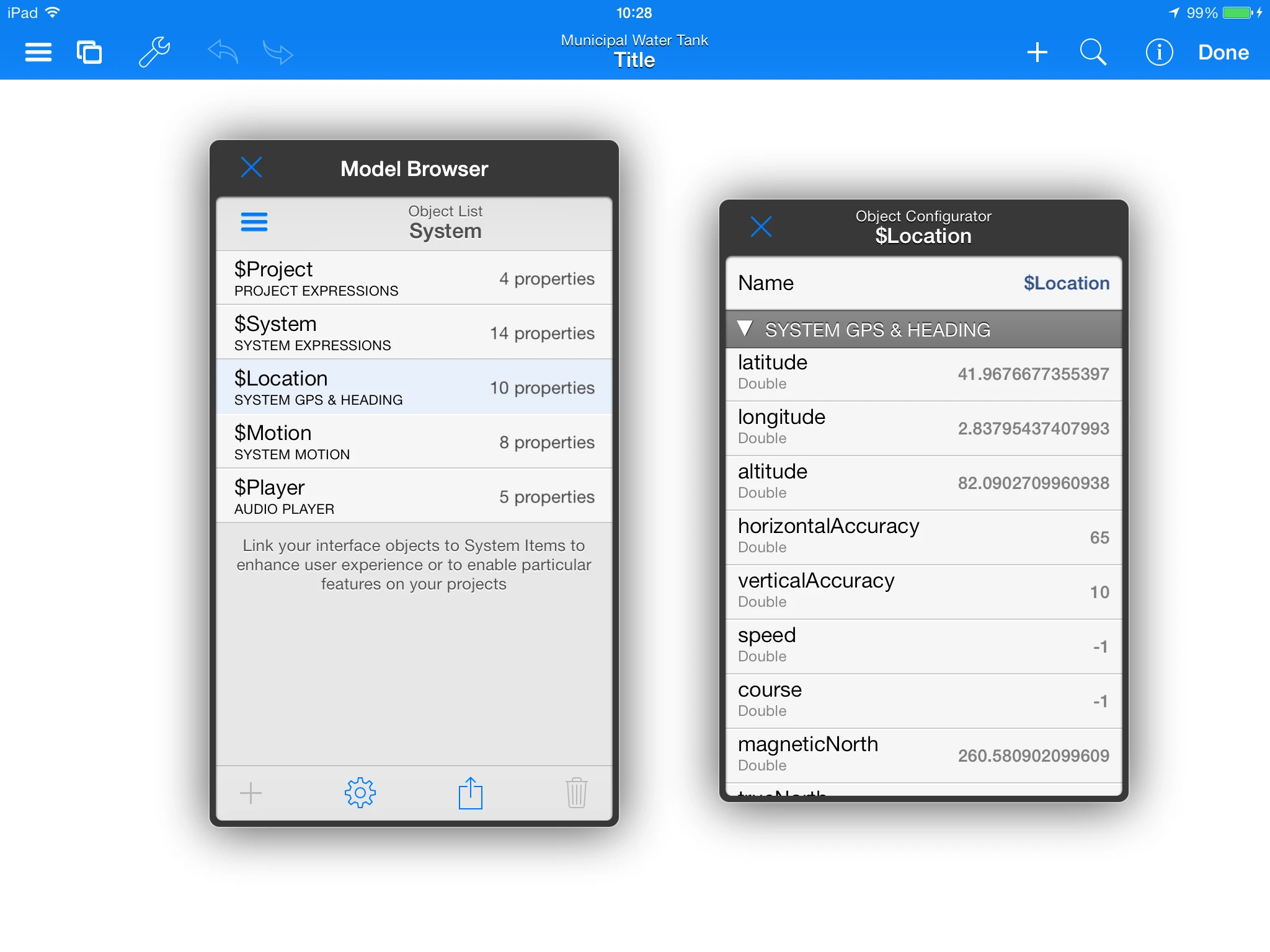
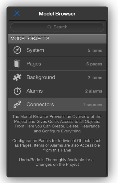
The Object Model is fully visible and accessible through the
Model Browser.
Model Browser.png
5.1 The Model Browser and Main Object Types
From the Model Browser you access the Object Model of your project.
This is equivalent to say that all the objects of your projects are
accessible from the Model Browser.
Furthermore, the Model Browser presents a hierarchical view of your
project. In the section named 'Objects Reference' a description of each
object type and its properties is provided in more detail.
The available main object types are listed next:
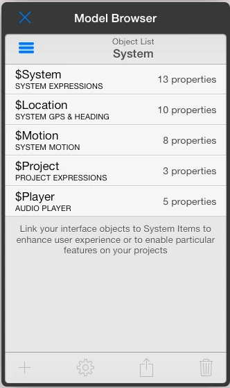
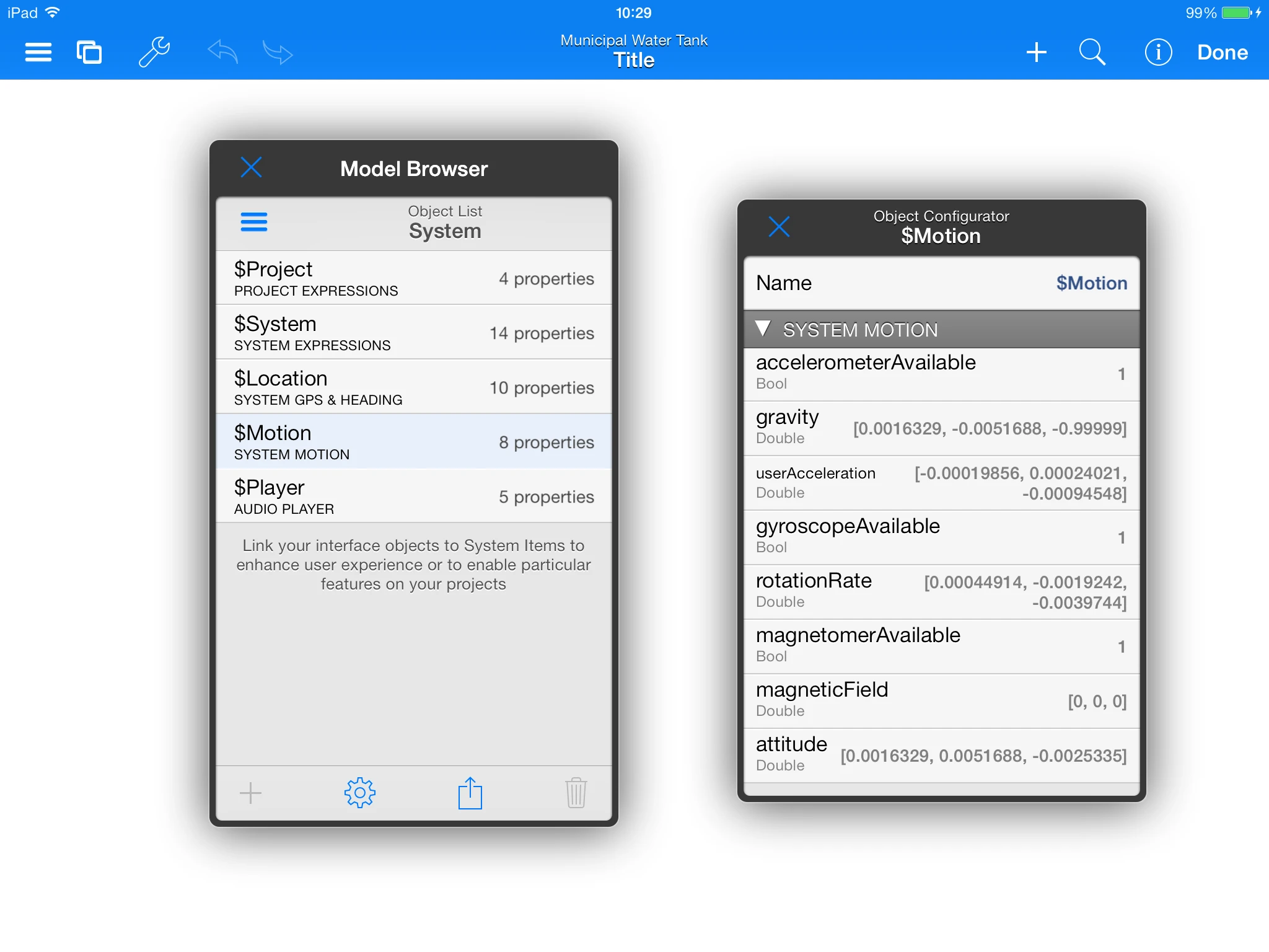
System Objects.
Represent objects that provide real time iPad sensor information or
access to project related properties.
Captura de pantalla 2013-12-16 a les
9.13.39.png
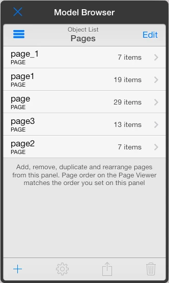
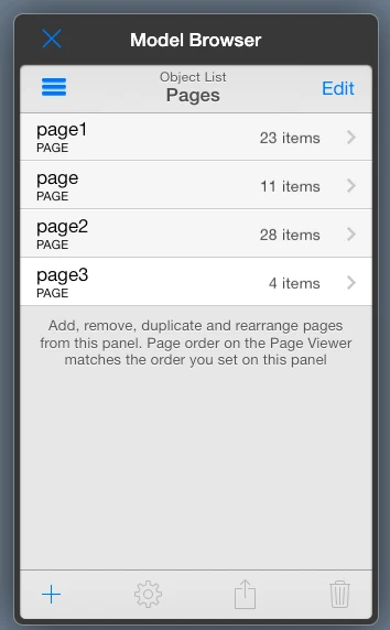
Pages.
The pages that your project contains. In pages you place visual items
that can be of a variety of types.
Captura de pantalla 2013-12-16 a les
9.15.29.png
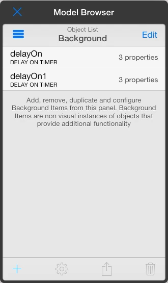
Background.
They are objects that do not have a visual component but you can use
on your project.
Captura de pantalla 2013-12-16 a les
9.17.04.png
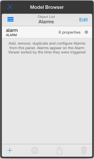
Alarms.
You set alarm or any arbitrary event conditions that will be
displayed on the Inspector Panel when triggered.
Captura de pantalla 2013-12-16 a les
9.18.26.png
Users.
You can create users on a project basis.
Data Loggers.
Data Loggers allow you to log historical values on database
files.
REST Connectors.
REST Connectors represent connections to web services that may adopt
the REST architecture.
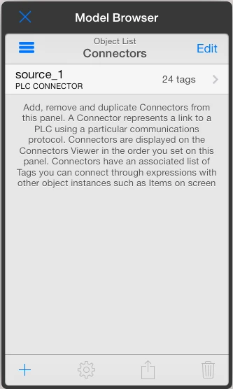
PLC Connectors.
PLC Connectors represent connections to PLCs. A connector includes
PLC communication settings and PLC tags.
Captura de pantalla 2013-12-16 a les
9.19.28.png
5.2 Object Properties
Objects in the HMI Editor app have Properties.
Particular properties may represent object states or visual
conditions.
Properties are identified in expressions by object name followed by a
dot and the property name.
objectName.property
You connect object properties together to add dynamic functionality
to your HMI projects. Properties are connected through expressions.
Example:
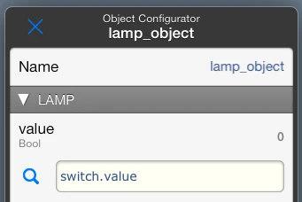
Let's suppose we have on a page a switch control and a
lamp indicator which are named as such. We want to turn the
lamp on/off with the switch control. To do so we need to enter the
switch value on the value property of the lamp.
Captura de pantalla 2014-02-14 a les
9.40.58.png
By entering the switch.value into the value
property of the lamp we achieve the desired effect because when
the switch changes a change event will propagate a change to
the value property of the lamp
Captura de pantalla 2014-02-14 a les
9.42.56.png
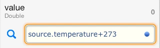
Notice that we entered this in the value property of the lamp,
not the switch. This may seem odd before you are used to it or if you
come from traditional HMI systems, but you just need to think on terms
of a spreadsheet to see why this works. On a spreadsheet let's assume
you want cell 'A1' to follow the value of cell 'A0'. You would enter
'=A0' in cell 'A1'. This is exactly how the HMI Editor app works, we
enter 'switch.value' in 'lamp.value' because we want the lamp to follow
the switch.
Object Properties are accessible through the Object
Configurator which is available from the "Configure" menu item
upon selecting an object on screen or by tapping the "gear" icon for an
object on the Model Browser.
5.2.1 Property Kinds
Object Properties can be read/write but some of them are
read only,(particularly on system items) or constants.
You identify the kind of properties by how they are presented or what is
allowed for them on the Object Configurator.
Read Only.
Read only properties are mostly used on system objects. They usually
provide real time information that can not be set by users or in general
any data value that can not be edited.
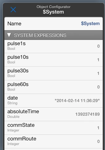
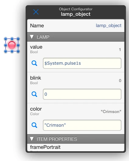
An example of a Read Only property is '$System pulse1s'
Read / Write.
Most properties on regular objects are Read/Write. On the Object
Configurator they provide a field where you can enter an expression. In
particular, Read/Write properties are identified because they present an
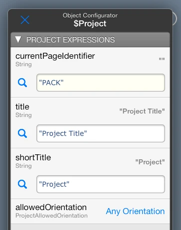
entry field with light yellow background.
An example of a Read/Write property is '$Project
currentPageIdentifier'
Constants.
Constant properties are similar to Read/Write properties except that
any expression or value entered on them can not be changed at runtime.
Constant properties are identified by the presence of an entry field
with white background.
An example of a Read/Write property is '$Project title'
5.2.1 Property Data Types
Object Properties can be of a variety of data types, such as
Integer, Double, String and so on.
It is important not to confuse Property Data Types with Expression
Result Types as they may not always be related. Particularly, Property
Data Type represents the type that semantically best describes the
Property, while Expression Result Types do carry a semantically agnostic
meaning.
For example, a string representing a color name can be assigned to a
Property of type Color, but it will still remain a String and
will be simply treated as such by the Expressions Engine.
The concept of Property Data Types abstracts expression result types
from their intended actions on properties, thus adding a flexibility
layer on the use of data types in expressions. For example a Color can
be physically represented by a String or by a Number in expressions, and
yet be assigned to the same property of type Color.
Property Data Types are shown just below Property Names on the Object
Configurator. Some of the most used are Integer, Bool,
Color, Double, Range, Url,
FontName, FormatString, Orientation,
TextAlignment, and more.
Property Data Types are enumerated and explained in more detail for
particular objects on the Object Reference section when relevant.
6 Expressions
Expressions can be entered on read/write properties and provide an
advanced way to customize various aspects of the interface and behavior
of HMI Pad projects.
You can combine Object Properties with operators and
methods to produce custom results and assign them to other
Properties. Object Properties are referred in expressions by using a dot
notation as described in the Object Properties section
Captura de pantalla 2013-12-16 a les
10.05.44.png
Event Driven Architecture.
Expressions in HMI Pad System are stored in a compiled form and are
executed by an event-driven engine. The execution engine keeps
expression reference information in a way that value changes trigger
expression evaluation. The engine is not endlessly executing 'for' loops
but only change events.
References to dependent expressions create a tree like network where
all expressions may have links to other expressions. When a PLC tag
changes, or an user interacts on a control, a change event is
originated. This event, that occurs at some point in the expressions
network, is propagated through the relevant links to reach only the
expressions that need to know about it, generally only a few.
The result is that expressions execution time is basically
independent of project sizes or the total number of expressions defined
in projects. The Event Driven Architecture is specially suitable for
running HMI projects in the constrained environment of a mobile device
and still be able to support very big projects with no noticeable
performance penalties.
Another responsibility of the Expressions Engine is to determine the
minimum set of data that is required at a given time to keep a
consistent interface. This is translated to the minimum set of tags to
poll and is notified to the Communications Module so no tags are polled
unnecessary at any given time. The Communications Engine then
automatically groups and optimizes command requests to PLCs for minimum
communication overhead. All these processes, including communications,
happen on a secondary execution thread so users never feel or notice
them.
The ultimate result is highly responsible HMI projects with controls
that respond and react quickly to user actions and fast updates of
interface elements.
Analogy with an Excel Spreadsheet
To help to understand the whole concept of the app it may be helpful
to think on it as a Excel spreadsheet and compare what Excel and HMI
Editor do. Indeed the behavior of the expressions engine on Excel and
HMI Editor are very similar in concept.
In the case of Excel you have Cells where you enter formulas. Excel
Cells connect to other cells through expressions. For example, in cell
A2 you can write =B1+B4. In the context of Excel, when
the value of B1 or B2 changes the value of A2
is automatically updated.
So this is exactly what HMiPad does. Instead of Cells we have Objects
with Properties. On the HMI Editor app an Object Property is the
equivalent of an Excel Cell. You connect Object Properties as you would
Excel Cells. On Excel you refer to Cells by Column-Row (example
B1) On HMI Editor you refer to Object Properties by their names
using a dot notation (example numberField.value).
Unless Excel Cells HMI Editor Object Properties have a meaning and
perform a particular action, thus when you make them to change there is
an effect, possibly a visual one such as changing a Color.
Basically, understanding the concept unlocks the full power of the
app. Expressions can be very simple or extremely complex, and as we
evolve the app more Objects with more Properties will be added.
Using Expressions.
HMI Editor expression syntax is based on the open source Ruby
scripting language syntax. For basic operations this syntax is similar
to that of the ‘C’ programming language and virtually identical to all
modern scripting languages.
The Ruby language was chosen because it features a clean, easy to
learn, object-oriented syntax with a particular focus on expressions
allowing for practical ways to represent and dealt with several data
types and formats with great flexibility. HMI Editor supports most
operators including all common Logical, Arithmetic and Comparison
operators, as well as commonly used Ruby functions and methods.
Support of Ruby expressions in HMI Editor is a subset of the Ruby
language. Expressions are not, and do not pretend to be a complete
implementation of Ruby. In some cases we provided a single way to
accomplish something that on Ruby can be done in several ways, and in
other cases we integrated several functionalities in single methods
instead of implementing all of them. So it is important to refer to this
manual if you are also using a Ruby tutorial to determine what it is
actually supported on HMI Editor and which behavior differences may
apply.
For those who already used Ruby, one of the most obvious differences
between ‘real’ Ruby and HMI Editor is the treatment of boolean values.
Ruby treats everything as object pointers, including numbers, while HMI
Editor keeps the traditional ‘C’ like behavior. For example, in Ruby any
number used in a boolean expression is a true value even if it
holds a zero, just because it exists as a pointer. HMI Editor, on the
other hand, will still take 0 (zero) as false and non-zero as
true, in the traditional sense of earlier programming
languages, and hopefully in accordance to what PLC programmers would
expect or feel more comfortable with.
You should always use values expressed in engineering units when
using expressions in HMI Editor. The HMI Pad expressions engine does not
have a notion of PLC raw values, as this is handled by the
communications component of the app.
When using expressions in your project you must be aware of the
following:
Object and Property names in expressions are case
sensitive. This means that an object property named
textField.value will not be the same than another one named
textfield.value.
Logical or Comparison operators assume non-zero values to
be true and zero values to be false. The
result of a Logical or Comparison operator, however, is always a value
of 0 or 1.
Comparison operators are non-associative. This
means that expressions such as a<b<c are not valid. You must use
a<b && b<c instead.
Assignments in expressions are not supported.
Therefore expressions such as condition && (intProperty = 3 )
will cause a syntax error on the assignment operator. Do not confuse the
assignment operator = with the the equality operator
== which is fully supported.
An expression is executed only when at least one of the
referred object properties change. The process is
totally transparent and integrators might not need to know about how it
works underneath. However, keeping the event driven nature of HMI Pad in
mind can help integrators to understand why and when dependent object
properties including PLC tags will be written or alarms will trigger as
a consequence of an user interaction or a PLC Tag change that originated
a cascade of change events.
Expressions containing Logical operatorsare no exception to the event driven design. They will
be fully executed even if a change occurs on the right side of the
Logical operator. For example the expression condition1 &&
condition2 would be always false if condition1 is
false, however it will execute anyway as a consequence of a
change on condition2. Although the expression result will not change (it
will remain false), the engine will still send a change
event to any depending expressions, which could potentially cause
other effects such as a PLC tag rewrite if the expression was linked to
a PLC tag.
Expressions can not create circular or recursive
references. This means that a result of an expression can not
be refitted to another expression that ultimately would send a
change event to the originating expression. This is not allowed
at any level on the expressions execution chain. For example the
following expression textField.value+1 on the value property of an
object named textField is not valid because textField.value creates a
circular reference around the value property. Note that HMI Editor
essentially behaves as a SpreadSheet program and this restriction also
applies on SpreadSheet programs..
6.1 Data Types in Expressions
Expressions in HMI Editor support the following primitive data types:
Number, String, Array,
Dictionary, AbsoluteTime, and
Range. other native types include
Point, Size, and
Rect,
Appropriate operators and methods allow for
conversion among types and to perform custom operations with great
flexibility. See the following sections for a discussion on methods and
operators.
Mixing different data types such as Numbers, Strings or Arrays is
only possible through the use of the appropriate operators and
methods that result in compatible types. A direct consequence
is, for instance, that you can not concatenate a number to a string
unless you convert the number to a string first. Also, some operators
have particular semantics depending on type. This is just like most
modern scripting languages including Ruby. On the following sections we
discuss further on this and on other subjects.
Numeric values.
Numeric values in expressions are internally stored as Double Float
values (64 bits) All Arithmetic, Logical and Comparison operations are
performed as Double Float operations. You may never expect to obtain
truncated values from arithmetic calculations.
The above statement may change in the future to give support for
true integer arithmetic. Currently, an implicit conversion to an integer
type is only performed for bit or bitwise operations on numbers, and
indexed access to string or array elements. In other cases you can use
the to_i method to explicitly get the integral part of a numeric value
according to your needs.
Constant numbers can be represented with optional decimal point and a
base 10 exponent. Additionally, hexadecimal and binary notations are
supported by using the 0x or 0b prefixes. The special
forms true, false+inf and -inf are
supported as well.
Examples:
-1.42 (decimal representation)
1.1666e+2 (decimal representation with exponent)
0xe0af (hexadecimal representation)
0b011011101 (binary representation)
true (same as 1)
false (same as 0)
-inf (very big negative number)
+inf (very big positive number)
Strings.
Strings are arbitrary sequences of characters that are manipulated as
a whole,. Several operations can be performed on strings such as
concatenate, split or substring extraction by using the appropriate
operators or methods. String literals are represented
enclosed in double quotes. Strings are internally encoded in a
compatible type (usually UTF8)
Examples :
"This is a literal string"
"Дискретные датчики"
"ピーエルシーのアラーム表示"
Arrays.
Arrays are-indexed collections of data values. Each element in an
array is associated with and referred to by an index.
Array indexing starts at 0. A negative index is assumed relative to
the end of the array, that is, an index of -1 indicates the last element
of the array, -2 is the next to last element in the array, and so
on.
Arrays can hold values of any data type such as Numbers, Strings,
Dictionaries, Arrays and so on. Arrays can be created in expressions by
using its implicit form consisting on separating their elements by
commas and enclosing them in square brackets.
Example:
["element at index 0", 123.4, [ 33, obj.value]]
The above expression represents an array of three elements.
At index 0 we have a literal string: "element at index 0".
At index 1 we have a numeric value: 123,4.
At index 2 we have an array of 2 elements with the number 33 and the
variable ‘temperature’ as their components
Elements of the referred array can be accessed by index as shown
next:
["element at index 0", 123.4, [ 33, obj.value]][1] would return
123.4
["element at index 0", 123.4, [ 33, obj.value]][-3] would return
"element at index 0"
["element at index 0", 123.4, [ 33, obj.value]][-1][0] would return
33
["element at index 0", 123.4, [ 33, obj.value]][2][1] would return
the actual value of obj.value
or assuming that the array is stored on an Object Property named
exp.value the above is equivalent to:
exp.value[1] would return 123.4
exp.value[-3] would return "element at index 0"
exp.value[-1][0] would return 33
exp.value[2][1] would return the actual value of
obj.value
Dictionaries.
Dictionaries are collections of unique keys and their values. They
have some similarity to Arrays but where an array uses an integer as in
index, a Dictionary allows you to use any data type as a key to retrieve
a value.
Keys on a dictionary can be any data type but Strings, Numbers and
Absolute Times are the most obvious choices.
Values on a dictionary can be of any data type such as Numbers,
Strings, Dictionaries, Arrays and so on. Dictionaries can be created in
expressions by using its implicit form consisting on separating their
key:value elements by commas and enclosing them in curly brackets.
Example 1:
{"red":"rojo", "blue":"azul"}
The above expression represents a dictionary of two elements.
For key "red" we have the string "rojo"
For key "blue" we have the string "azul"
Elements of the referred dictionary can be accessed by key as shown
next:
{"red":"rojo", "blue":"azul"}["red"] would return "rojo"
{"red":"rojo", "blue":"azul"}["blue"] would return "azul"
or assuming that the dictionary is stored on an Object Property named
exp.value the above is equivalent to:
The above expression represents a dictionary of two elements.
For key "red" we have the dictionary {"sp":"rojo", "fr":"rouge"}
For key "blue" we have the dictionary {"sp":"azul", "fr","bleu"}
Assuming that the dictionary is stored on an Object Property named
exp.value elements can be accessed by key as shown below:
exp.value["red"] would return {"sp":"rojo", "fr":"rouge"}
exp.value["red"]["sp"] would return "rojo"
exp.value["red"]["fr"] would return "rouge"
Absolute Time values.
Absolute Times are similar to Numeric values with a special
meaning.
An Absolute time is measured in seconds relative to the absolute
reference date of January 1 1970 00:00:00 GMT. A positive value
represents a date after the reference date, a negative value represents
a date before it. For example, the Absolute Time 1,000,000,000 seconds
translates into the calendar time 9 September 2001 01:46:40 GMT
A Specific variable, $System.absoluteTime is provided to obtain the
current time. Specific methods are also provided to extract interesting
calendar fields from an Absolute Time value, as well as to get custom
string representations of calendar dates.
Examples
$System.absoluteTime may return 1355481788 (seconds count since the
reference date)
$System.absoluteTime.year may return 2013
$System.absoluteTime.timeformatter("yyyy-MM-dd HH:mm:ss") may return
the string "2013-01-20 10:15:34"
Ranges.
A Range represents an interval of numeric values with a beginning and
an end. A range can be created with its implicit form consisting on the
lower and upper values separated by two points
Examples
0..100 represents the interval from 0 to 100 inclusive
-10..30 represents the interval from -10 to 30 inclusive
6.2 Supported Operators and Operator precedence
The following table shows the available operators and its precedence.
The table lists all operators from highest precedence to lowest.
OPERATOR
Description
Associativity
()
Parentheses (grouping).
from inner to outer
. () []
Method/Property selection, Method/Function call, Array or String
subscript
left-to-right
! ~ + -
Logical NOT, Bit Complement, Unary plus, Unary minus.
Operators are used in the
usual way as per the Ruby or “C” language. Depending on data types
involved the same operator may have a different meaning. See Methods, Expressions and more about
Operators.for further information.
The Expression List Operator (or comma operator) is not available on
regular Ruby and it has a different meaning on "C"
6.3 Functions, Methods and more about Operators
Methods can be applied to intermediate expressions or object
properties to perform type conversions or to achieve particular
requirements. They are like computer language functions that perform
particular tasks. Not all methods are applicable to all types
and their meaning can vary depending on type. Methods are
invoked by appending a dot (method selector operator) followed
by its name to the variable or subexpression they apply to.
Operators can also have a different meaning depending on the
data type they are applied to.
In the following tables we describe the function of the applicable
operators and methods depending on data type.
6.3.1 Numeric Operators and Methods
NUMERIC
Description
num operator num2
Arithmetic, comparison, logical operators produce the expected usual
results. Available operators are listed on the operators precedence
table shown earlier. The bitwise and complement operators extract the
integral part of the operands before computing the result
Example: 2+2 returns 4
Example: 0b1000 + 0b0001 returns 0b1001 (this is 17(dec))
Example: 0b1000 & 0b0001 returns 0b0000 (this is 0(dec))
Example: switch.value || switch2.value returns 1 (true) if one of
them is true
num[n]
Returns bit n from the integral part of num. Bit 0
is the least significant bit. The result can be only 0 or 1.
For example, number 3 is 0b011:
Example: 3[0] returns 1
Example: 3[1] returns 1
Example: 3[2] returns 0
num.to_i
Returns the integral part of num.
Example: 3.666.to_i returns 3
Example: 2.78.to_i returns 2
num.to_f
Returns the same num.
num.to_s
num to_s(fmt)
Returns a string representation of num optionally formatted
according to fmt. For a description of possible format
specifiers refer to the format function.
Example: 3.666.to_s("%03d") results in “003”
Example: 3.666.to_s(“%04.1f") results in”03.7"
Example: 3.666.to_s results in "3.666"
Example: 25.to_s("%02.1f ºC") results in "25.0 ºC"
(Note that specifying a format in to_s is not a standard
feature of Ruby)
num.chr
Returns a string containing a single character represented by the
Unicode character code num.
Example: 72.chr would return "H"
num.abs
Returns the absolute value of num.
Example: (-3.66).abs would return 3.66
num.round
Returns num rounded to the nearest integer.
Example: (3.66).round would return 4
num.floor
Returns the largest integer that is less than or equal to
num.
Example: (3.66).floor would return 3
num.ceil
Returns the smallest integer that is greater than or equal to
num.
Example: (3.66).ceil would return 4
Example: (3.1).ceil would return 4
num.between (min,max)
Returns 1 (true) if min <= num <=
max, otherwise 0.
Example: 5.between(1,10) returns 1
Example: 0.between(1,10) returns 0
num.clamp (min,max)
Returns num limited to the [min, max]
range.
Example: (-2).clamp(0,10) returns 0
Example: 15.clamp(0,10) returns 10
Example: 5.clamp(0,10) returns 5
num.zero
Returns 1 if num equals 0, otherwise 0.
num .positive
Returns 1 if num is greater than 0, otherwise 0.
num .negative
Returns 1 if num is less than 0, otherwise 0.
num.even
Returns 1 if the integral part of num is even, otherwise
0.
Example: 4.even returns 1
Example: 5.even returns 0
num.odd
Returns 1 if the integral part of num is odd, otherwise
0.
num.class
Returns the literal string "Number". The class method is
available on any value and returns its type name ("Number", "String",
"Array", "Hash", "Point", "Size", "Rect", "Range", "AbsoluteTime").
6.3.2 String Operators and Methods
STRING
Description
"characters"
Creates and returns a string containing the sequence of characters
written between quotes.
str[n]
Gets the Unicode representation of the character at index n
in str. If n is negative indexes start at the last
character. Generates an error when attempting an out of bounds
access.
Example: "Hello world"[0] returns 72 (72 is the Unicode character
representation of ‘H’)
Unicode representation of English Language characters fully match the
7 bit standard ASCII character representation.
str[n,m]
Substring. Returns a substring of str starting at n
and continuing for m elements. Always returns a string. Returns
an empty string "" when access is out of bounds, m can
not be negative. If n is negative indexes start at the last
character.
Example: "Hello world"[0,4] results in "hell"
Example: "Hello world"[-5,5] results in "world"
Example: "Hello world"[6,5] results in "world"
str+other_str
Concatenation.
Example "hello" + "world" will give "hello world"
str1 comparison_operator
str2
String Comparison.
Returns 1 or 0 (true or false) when comparing two strings for
equality or as if they were sorted in a dictionary.
Example "alpha"<"beta" returns true because “alpha” is
before “beta” in a word dictionary.
Example "alpha"=="beta" returns false because “alpha” is
different than “beta”.
Example “alpha"!="beta" returns true because”alpha” is
different than “beta”.
str.to_i
Parses a str into an integer value or returns 0 if not
possible
Example: "3".to_i returns 3
str.to_f
Parses a str into a floating point number or returns 0 if
the conversion is not possible
Example: "3.2".to_f returns 3.2
str.to_s
str.to_s(fmt)
Returns str. formatted according to fmt if
specified, or str otherwise. Only the “s” format specifier is
relevant for strings.
Example: "World".to_s("Hello %s") would give " Hello World "
str.split(str2)
str.split
Creates an array of strings by splitting str using
str2 as a delimiter but not including it. If str2 is
an empty string it splits str into each one of its characters.
If str2 is not given it returns an array with str as
the single element.
Example "Hello World".split(" ") returns ["Hello","World"]
Example "08-04-2014".split("-") returns ["08","04","2014"]
Example "08-04-2014".split("") returns
[“0","8","-","0","4","-","2","0","1","4"]
Returns a copy of str with all characters in upper case.
Example "Hello".upcase returns "HELLO"
str.downcase
Returns a copy of str with all characters in lower case.
Example "Hello".downcase returns "hello"
str.capitalize
Returns a copy of str with the first character in upper case
and all remaining characters in lower case.
Example "hello WORLD".capitalize returns "Hello world"
str.strip
Returns a copy of str with leading and trailing whitespace
removed.
Example " hi ".strip returns "hi"
str.reverse
Returns a copy of str with the order of characters
reversed.
Example "abc".reverse returns "cba"
str.start_with(pre)
Returns 1 (true) if str begins with the substring
pre, otherwise 0.
Example "Hello".start_with("He") returns 1
str.end_with(suf)
Returns 1 (true) if str ends with the substring
suf, otherwise 0.
Example "Hello".end_with("lo") returns 1
str.include(sub)
Returns 1 (true) if the substring sub appears anywhere in
str, otherwise 0.
Example "Hello".include("ell") returns 1
str.count(sub)
Returns the number of non-overlapping occurrences of the substring
sub in str.
Example "abcabc".count("a") returns 2
str.sub(find, replace)
Returns a copy of str with the FIRST occurrence of
find replaced by replace. If find is not
found, str is returned unchanged.
Example "aXbXc".sub("X","-") returns "a-bXc"
str.gsub(find, replace)
Returns a copy of str with ALL occurrences of find
replaced by replace.
Example "aXbXc".gsub("X","-") returns "a-b-c"
str.class
Returns the literal string "String".
6.3.3 Array Operators and Methods
ARRAY
Description
[d1,d2,...]
Creates an Array with the elements d1, d2 and so
on. Array elements can be any data types including numbers, strings,
ranges, dictionaries or other arrays.
Example: ["one","two","three"] would create an array containing three
string elements.
Example: [1,4,6] would create an array containing three integer
elements.
Example: ["one",2,"three"] would create an array containing three
mixed type elements.
Example: the following expression [1,"two",[10,"eleven"]] would
create an array containing three elements: the array will have a number
at position 0, a string at position 1 and a two elements array at
position 2.
arr[n]
Get element at index n from arr. If ‘n’ is negative
indexes start at the last character. Generates an error when attempting
an on out of bounds access
Subarray. Returns a subarray of arr starting at n
and continuing for m elements. Always returns an array. It will
return an empty array [] when access is beyond limits. m can
not be negative.
Same as min_by but returns the element with the largest
[k] value.
arr.all
Returns 1 if every element of arr is truthy (a
non-zero number or a non-empty string), otherwise 0.
Example: [1,2,3].all returns 1
Example: [1,0,3].all returns 0
arr.any
Returns 1 if at least one element of arr is truthy.
arr.none
Returns 1 if no element of arr is truthy. Equivalent to
!arr.any.
arr.map(k)
For an array of hashes, returns a new array containing the value at
[k] of each element. For an array of arrays, k must be
a numeric index. Missing values become error elements (use
.compact to remove them).
arr.reject(...)| >
Opposite of select: keeps elements where the | > condition
does NOT hold. Same argument forms as | > select.
arr .dig(k1,k2, ...)
Recursively descends into nested hashes or arrays, extracting
value[k1][k2][...]. For arrays the corresponding key must be a
numeric index. Generates an error if any key is missing or out of
range.
Example: {"a":[10,20,30]}.dig("a",1) returns 20
arr .zip(other)
Returns an array of pairs interleaving elements from arr and
other. The result has length 2 * min(arr.length,
other.length).
Creates a Dictionary with the specified key:value pairs
(k1:v1, k2:v2 and so on) and returns
it.
Keys can be any data type but most often you will use numbers,
strings or absolute times.
Values can be any data type including numbers, strings, ranges,
arrays or other dictionaries
Keys can not be repeated in a dictionary, so if two or more keys are
identical only the last one appearing on the comma separated list will
be used.
Example1: the following expression {1:"one", 2:"two"} would create a
dictionary containing two elements, the dictionary will have the string
"one" for key 1 and the string "two" for key 2
dict[k]
Get value for key k from dict. Generates an error
if k is not in the dictionary.
Example: {1:"one", 2:"two"}[1] returns "one"
Example: {"one":1, "two":2}["one"] returns 1
dict1 + dict1
Returns a new dictionary containing all key:value pairs of
dict1 and dict2 If the same key is present in
dict1 and dict2 the resulting dictionary will get the
value in dict2 for that key
Returns the number of elements -same as key:value pairs- in
dict.
Example: {1:"one", 2:"two"}.length results in 2
dict.keys
Returns an array containing all the keys in dict. The length
of the returned array will be the same as the length of dict
.Since dictionaries are not an ordered collection the order of elements
in the returned array is undefined. You should never assume that keys
will be returned on a particular order. Since keys are unique on a
dictionary the returned array will contain unique elements too.
Returns an array containing all the keys in dict. The length
of the returned array will be the same as the length of dict.
Since dictionaries are not an ordered collection the order of elements
in the returned array is undefined. You should never assume that values
will be returned on a particular order. Repeated values in the
dictionary will result in repeated elements in the returned array.
Returns a flat array [k1,v1,k2,v2,...] containing each key followed
by its value. Order is undefined.
Example: {"a":1,"b":2}.to_a returns ["a",1,"b",2]
dict.class
Returns the literal string "Hash".
6.3.5 Absolute Time Operators and Methods
ABSOLUTE TIME
Description
time + num
num + time
Adding a number num to an absolute time time
results in the absolute time incremented by the number of seconds
specified in num. Note that it is not possible adding two
absolute times
Example: $System.absoluteTime + 0.1 will return a time that is 100
milliseconds ahead of now.
time - num
time2 - time1
Subtracting a number num to an absolute time time
results in the absolute time decremented by the number of seconds
specified in num.
Subtracting two absolute times will result in a number representing
the elapsed time between the two expressed in seconds
Example: $System.absoluteTime - 60 will return the time that was 1
minute ago.
t1 comparison_operator t2
Absolute Time Comparison.
Returns 1 or 0 (true or false) when comparing two absolute times. In
the context of absolute times a time is greater than a base time if it
is a time that happened or will happen after the base time.
time.to_f
Converts an absolute time to a number representing the seconds count
since the reference date
Example $System.absoluteTime.to_f may return 1355481788
time.timeformatter(fmt)
The timeformatter method returns a string representation of
an absolute time given a format string.
When applying this method time is a numeric value meant to
hold a specific point in time expressed in seconds relative to
1-Jan-1970, for example an absolute time value provided by the
‘$System.absoluteTime’ object property. The fmt parameter is a
format sting as specified in the ‘Unicode Technical Standard #35,
Appendix F’. The method will return a string representation of the date
and time for the given absolute time taking into account the current
time zone location of the device.
For more information on valid format strings for the fmt
parameter you can have a look at:
When looking at this spec be aware that character symbols in the
format string are case sensitive and thus they may have different
meaning depending on case, for instance ‘yy’ will represent a year
whereas ‘YY’ will represent a week of year.
Example:
$System.absoluteTime.timeformatter("yyyy-MM-dd HH:mm:ss") may return
the string "2012-12-28 10:15:26"
time.year
Returns the Gregorian Calendar year for an absolute time
time at the current time zone location
time.month
Returns the Gregorian Calendar month for an absolute time
time at the current time zone location. Range of returned
values is 1 to 12
time.day
Returns the Gregorian Calendar day for an absolute time
time at the current time zone location. Range of returned
values is 1 to 31
time.wday
Returns the day of the week for an absolute time time at
the current time zone location, 0 is Sunday, 1 is Monday and 6 is
Saturday.
time.yday
Returns the day of the year for an absolute time time at
the current time zone location. Range of returned values is 1 to
366
time.week
Returns the week of the year for an absolute time time at
the current time zone location. Range of returned values is 1 to 53
time.hour
Returns the Gregorian Calendar hour for an absolute time
time at the current time zone location. Range of returned
values is 0 to 23
time.min
Returns the Gregorian Calendar minutes for an absolute time
time at the current time zone location. Range of returned
values is 0 to 59
time.sec
Returns the Gregorian Calendar seconds for an absolute time
time at the current time zone location. Range of returned
values is 0 to 59
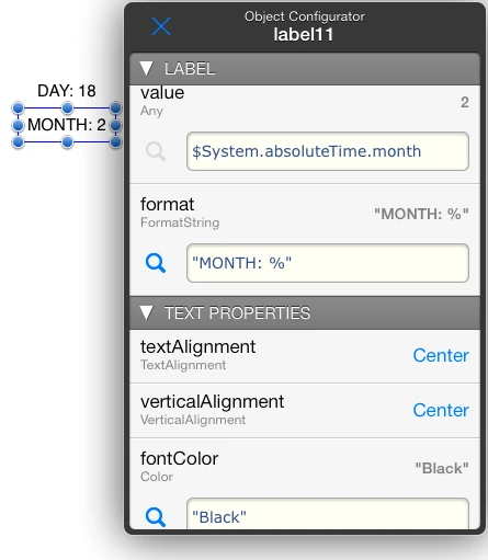
The following illustration demonstrates the use of a time expression
on a label item.
Captura de pantalla 2014-02-18 a les
12.37.00.png
6.3.6 Range Operators and Methods
RANGE
Description
num1..num2
Creates and returns a range starting at num1 and
ending at num2 inclusive
range.begin
Returns the staring value a range
Example: (0..9).begin returns 0
range.end
Returns the staring value a range
Example: (0..9).end returns 9
6.3.7 Rect, Point and Size Methods
RANGE
Description
rect.origin
Returns a point type value representing
the top left coordinates of rect
rect.size
Returns a size type value representing the
width and height of rect
point.x
Returns the x coordinate of point
as a number
point.y
Returns the y coordinate of point
as a number
size.width
Returns the width of size as a
number
size.height
Returns the height of size as a
number
6.3.8 MATH Methods
MATH
Description
Math.atan2(y,x)
Computes the principal value of the arc tangent of
y/x, using the signs of both arguments to determine
the quadrant of the return value.
The atan2() function is used mostly to convert from
rectangular (x,y) to polar (r,θ)
coordinates that will satisfy x = r*Math.cos(θ) and y =
r*Math.sin(θ).
In general, conversions to polar coordinates are computed in this
way:
r = Math.sqrt(x*x+y*y)
θ = Math.atan2(y,x)
Math.cos(x)
Computes the cosine of x (measured in radians)
Math.exp(x)
Calculates an exponential function (e raised to the power of x)
Math.log(x)
Calculates the natural logarithm of x.
Math.log10(x)
Calculates the base 10 logarithm of x.
Math.sin(x)
Computes the sine of x (measured in radians)
Math.sqrt(x)
Computes the non-negative square root of x
Math.tan(x)
Computes the tangent of x (measured in radians)
Math.PI
Returns the π constant number
Math.floor(x)
Returns the largest integer less than or equal to x.
** Deprecated starting from version 2.1. Please use
num.floor instead
Math.ceil(x)
Returns the smallest integer greater than or equal to
x.
** Deprecated starting from version 2.1. Please use
num.ceil instead
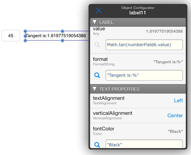
The following illustration uses a MATH expression to display a value
on a label item.
Captura de pantalla 2014-02-18 a les
12.32.33.png
6.3.9 Built-in Functions
FUNCTIONS
Description
format(fmt,...)
Returns a string where the list of arguments following fmt
is formatted according to fmt, fmt is a Formating
specification string.
Formatting specifications in fmt are essentially the same as
those of the sprintf function in the C programming language. Conversion
specifiers in fmt begin with % and are replaced by a formatted
string of the corresponding argument. A % character followed by another
% will yield the ‘%’ character. A list of supported conversion fields is
given on the next section.
Examples:
format("Room Temperature is: %4.1f", 25) will return the string "Room
Temperature is: 25.0"
format("%02d:%02d:%02d",hours,minutes,seconds) may return the string
"01:15:48" assuming the variables ‘hours’ ‘minutes’ and ‘seconds’
contain the given values.
format("Throughput: %4.1f%%", 25) will return the string "Throughput:
25.0%"
rand
rand(n)
Returns a semi-random number on a specific interval.
When no argument is given it returns a numeric floating point value
'r' in the range 0 <= r <1
When an integer argument is given it returns an integer value 'i' in
the range 0 <= i < n
Examples:
rand may return 0.28384618
rand(10) may return 7
6.3.10 System Methods
SYSTEM
Description
SM.color(r,g,b)
SM.color(r,g,b,a)
SM.color(str)
Returns a numeric representation of a color. You provide the RGB
color coordinates as values ranging from 0 to 255 in r,
g and b, with optional alfa a from 0 to 1
Alternatively you can provide a string with the color name in
str.
SM.deviceID
Returns an unique identifier string representing the iOS device the
app is running on. The returned string is always the same for the same
device but a different value is returned for different devices.
Returned values will look like this:
"846AB563-760E-45BA-8E9E-88BE1D0A5ED7"
SM.point(x,y)
Returns a point type value from its x, y
coordinates
SM.size(w,h)
Returns a size type value.with width w, and height
h.
SM.rect(x,y,w,h)
Returns a rect type value.with x, y top left
coordinates, width w, and height h.
SM.allFonts()
Returns an array of strings with all the available font names.
SM.allColors()
Returns an array of strings with all the available color names.
SM.encrypt(s,key)
Returns a string representing the encrypted version of the string
s by applying a symmetric AES256 algorithm using key
as the encryption key.
Example: SM.Encrypt("myString","aPassword") will encrypt "myString"
using "aPassword"
SM.decrypt(s,key)
Returns the original unencrypted string from the encrypted string
s by applying an AES256 decryption algorithm based on
key. This method will return the original string that was
passed as the first parameter to SM.encrypt provided the same
key was used.
Example: SM.decrypt(SM.encrypt("myString,"pass"), "pass") will return
"myString"
SM.mktime(y)
SM.mktime(y,m)
SM.mktime(y,m,d)
SM.mktime(y,m,d,h)
SM.mktime(y,m,d,h,mn)
SM.mktime(y,m,d,h,mn,s)
Returns an absolute time that is a representation of the time
period that is implicit on the parameters. In particular, it returns the
absolute time of the first instant of the intended passed in time
period.
You can use this method to provide a custom time reference to
data presenter objects.
Examples
SM.mkTime(2014) will return the first instant of year 2014 as an
absolute time
SM.mkTime(2014,2) will return the first second of February, 2014 as
an absolute time
SM.mkTime(2014,2,3) will return the first second of February, 3rd,
2014
SM.mkTime(2014,2,3,12) will return midday time on February, 3rd,
2014
SM.mkTime(2014,2,3,12,5) will return time on February, 3rd, 2014 at
12:05:00
SM.mkTime(2014,2,3,12,5,45) will return time on February, 3rd, 2014
at 12:05:45
6.4 Format specifiers for ‘format’ and ‘to_s’
The built-in function format returns a string formatted
according to a format string following the usual printf conventions of
the C language. In addition, format accepts %b for
binary. The to_s method also support formatting when applied to
numbers or strings.
HMI Editor. format specifiers adopt the following form:
%<flags><width><.precision>specifier
Where specifier is the most significant one and defines the
type and the interpretation of the value of the corresponding argument
(’<’ and ’>’ denote optional
fields).
For types supporting the to_s method format specifiers are
also applicable
The following format conversion specifiers are available:
FORMAT SPECIFIER
Description
format
function
support
to_s method
support
b
Binary integer
YES
YES
c
Single character
YES
YES
d,i
Decimal integer
YES
YES
e
Exponential notation (e.g., 2.44e6)
YES
YES
E
Exponential notation (e.g., 2.44E6)
YES
YES
f
Floating-point number (e.g., 2.44)
YES
YES
g
Use the shorter of e or f
YES
YES
G
Use the shorter of E or f
YES
YES
o
Octal integer
YES
YES
s
String or any object converted using to_s
YES
YES
u
Unsigned decimal integer
YES
YES
x
Hexadecimal integer (e.g., 39ff)
YES
YES
X
Hexadecimal integer (e.g., 39FF)
YES
YES
For the meaning and possible contents of the optional flags,
width, and precision fields refer to the sprintf
specification:
Since there is no need for the length field it is not
available neither in Ruby or HMI Editor.
6.5 The ternary conditional operator
The ternary conditional operator provide conditional execution of
expressions. Its syntax is the following:
expr ? expr1 : expr2
The expression above returns expr1 if expr is not
zero (true) or expr2 otherwise.
The ternary conditional operator executes when any of expr,
expr1, expr2 generate a change event. The result is
always updated and will be consistent with the values of expr,
expr1 and expr2 at all times. The execution will in
turn trigger relevant change events up the expressions tree just as any
expression would do.
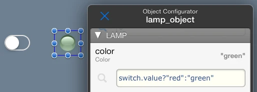
The resulting color will be always updated according to
switchColorSelection upon any change on
switchColorSelection, color1 or color2
values
Captura de pantalla 2014-02-14 a les
11.31.11.png
6.6 The ‘if-then-else’ clause
The if-then-else clause provide conditional choice of
expressions. It is used as follows:
if expr [then] expr1 [else expr2] [end]
Executes expr1 if expr is not zero (true). If
expr is zero (false) expr2 is executed instead. Items
between brackets are optional.
The if-then-else clause only attends to expr change events.
Any changes in expr1 or expr2 will not have an effect
until expr executes. Furthermore, if expr is
false and expr2 was not specified, the execution tree
is trimmed at this stage and no further execution up the expresion tree
will happen.
You should only use the if-then-else clause when the above is
required, otherwise use the ternary conditional operator.
The if-then-else clause is useful in cases where you want to achieve
a differential effect, for example to trigger an event when a condition
goes from false to true but not the opposite. This is
not possible with the ternary conditional operator because it will
always execute both ways.
Consider the following expression entered on the value
property of a lamp object:
if startButton.value then 1 else (if stopButton.value then
0)
The previous lines asume the existence of a start button
startButton and a stop button stopButton. When the
start button is touched 1 will be written to lamp.value. When
the stop button is touched 0 will be written to lamp.value.
Because we are using the if-then-else clause, no change event will be
sent to lamp.value upon release of the buttons.
Another use of the if then else clause is the implementation
of a counter.
Consider a background item named counter and the following
expression entered on its value property
if resetButton.value then 0 else (if incrementButton.value
then counter.value+1)
The resetButton and incrementButton buttons provide
in this case the interface for incrementing the counter
value.
NOTE: We recommend to restrict the use of the 'if-then-else' clause
to cases where it is strictly necessary as described above and only
where the ternary conditional operator would not work.
Ab-using or mis-understanding the purpose and consequences of using
it of may create uninitialized values or properties specially on first
project launch or update. It is important to always foresee such
circumstance and provide an initializer to values that otherwise would
never be valid.
For example on the counter example provided above, we incorporated a
reset button to allow users to initialize the counter to a valid initial
known state.
6.7 The Expression List Operator
The Expression List Operator is an advanced feature that enables you
to selectively execute one of several expressions based on the actual
flow of change events in the Expression Engine.
Its purpose is similar to the if-then-else clause but in
this case the result does not depend on a explicit condition but on the
last expression on the list that received a change.
Consider the following expression list.
exp1, exp2, exp3
We have a list of three expressions separated by commas. The result
of the above will be either exp1, exp2 or
exp3 depending on the one that last changed. For instance if
exp1 just received a change, then the result of the list will
be exp1 If now exp3 changes then the result will be
exp3
Note that the result is always the first expression in the list that
changed, For example the following expression list exp1+1,
exp1+2 will always return exp1+1 upon a change of
exp1 because it s the first in the list to change .
One particularly interesting use case of the Expression List Operator
is when you need to write a value to a PLC tag based on more than one
item on screen. For example you want to write a set-point value on a PLC
Tag based on user action on a slider or on entering a value on a number
field on the interface.
You can enter the following on the write_expression field of
the PLC tag
slider.value, numberField.value
In this case, a change on slider.value or the
numberField.value will result on the writing or the resulting
value to your PLC Tag
Captura de pantalla 2014-02-14 a les
11.34.16.png
6.8 Putting it all together. Advanced Expressions
Examples
You can use expressions in your HMI Editor project in many advanced
ways. Expressions provide a lot of power and flexibility and most of the
features of HMI Editor are unveiled through the advanced use of
expressions.
We present next some examples of advanced expressions involving
several operators, methods and data types to obtain particular results.
This is of course not exhaustive as you can use expressions for tasks
that we could not even imagine.
Converting an arbitrary number of seconds to hh:mm:ss
format
The following expression shows how to get a string in the form
‘hh:mm:ss’ from a numeric value containing seconds.In this example
x contains the total number of seconds to be converted to the
desired format.
The operators % and / are used to calculate hours, minutes, seconds
as numeric values. These are then truncated to integer with the
to_i method and successively converted to formatted strings
with to_s. The resulting individual strings are embedded into
an array and then joined by means of the the join method using
‘:’ as separator.
Instead of using the join method we could have used the
format function as a more convenient way. Consider the
following:
in this case the format specifiers in the format string are just
replaced with the relevant time values.
Calculating seconds from a string having the hh:mm:ss
format.
Just to illustrate what expressions allow to do let’s try now to get
the original seconds value from a string already in the hh:mm:ss format.
To do so we can use the following expression:
In this case we extract separately the hours, minutes and seconds as
numeric values from the string, we multiply them by 3600, 60 and 1
respectively and then add them to get the total number of seconds. The
extraction of each value from the original string is performed by the
split method using ‘:’ as delimiter. The relevant element from
the split array is obtained with the fetch method. We use 0 as
the default value for fetching.
Note that we could have used simple array indexing such as
t.split(":")[-3] to get each part of the original string but this would
lead to potential out of bound errors in case the original string had
some missing part. Particularly, if the original string did only contain
minutes and seconds, such as "50:30" ( 50 minutes, 30 seconds) the
referred indexed expression would give an out of bounds error as it
would attempt to access a non existing element (the one before the first
one).
Note also that in all cases we use negative indexing because we
interpret that the last part is always meant to be the seconds, the
previous to the last one the minutes and so on.
The proposed expression can be optionally optimized by storing the
split string in a temporary variable (background expression) so that the
splitting is only performed once. If we apply this optimization.the
final solution would look as follows:
t.split(":") <- we store this on the value
property of tspt
Creating a label that alternates between displaying the
current time and an arbitrary value
In this example we will create a label that shows a living digital
clock showing the current time. Every 5 seconds the time is alternated
with a temperature value given in an item named temperature. In
order to achieve this we enter the following expression in the
value property of a label item.
We use the ternary operator to switch between the time and the
temperature depending on the $System.pulse10 pulsating
property. For the clock we take $System.date and discard the
date portion by splitting it out. The temperature is presented formatted
with a custom prefix and suffix appended to the actual value.
We can alternatively use the format function to simplify a bit some
portions of the expression
Refer to this section for reference of all Object Property
descriptions.For classes of objects that share similar properties they
are presented hierarchically. The same hierarchy is shown in most cases
in form of table sections in the Object Configuration panel.
7.1 System Objects
They are special objects that provide device sensor data, and other
system or project related information.
7.1.1 $Project
The $Project Object contains properties that may affect the entire
project.
Captura de pantalla 2014-02-14 a les
11.58.16.png
PROPERTY
TYPE
DESCRIPTION
currentPageIdentifier
String
(read/write String)
When you set a string to this property the system searches for a page
with a matching pageIdentifier .If found, the system moves to
that page. Nothing happens if no page has a pageIdentifier matching the
string
Example: If you have two pages with pageIdentifiers
"PAGE1" and "PAGE2" and two buttons named button1 and
button2 you can use the ternary conditional operator like
this.
The Title that will appear on the tool bar when this project is
open.You can use this value for your own purposes as well.
shortTitle
(constant String)
Reserved for future use. You can still use this for your own
purposes.
allowedOrientation
(constant number)
Determines which orientations are available for the project on
the iPad interfaceIdiom. When you chose an allowed orientation, the
project is forced to display on that orientation. This property allows
you to design projects that do not support multiple orientations.
Any Orientation: Project pages will rotate and
display using their settings on both orientations.
Landscape Only: Project pages will keep
Landscape mode regardless of device orientation.
Portrait Only: Project pages will keep Portrait
mode regardless of device orientation
allowedOrientationPhone
(constant number)
This property has the same meaning than allowedOrientation
except that it refers to the iPhone/iPod interface idioms.
7.1.2 $System
The $System object provides the interface for using system or project
related info on your project:
PROPERTY
TYPE
DESCRIPTION
SMPulse1s
SMPulse10s
SMPulse30s
SMPulse60s
Bool
(read only Number)
They generate a square wave signal with the period implicit on the
variable name. They can be used to implement a Keep-Alive tag, to write
periodically a value on a PLC, or to trigger periodic events for any
purpose.
SMPulseOnce
Bool
(read only Number)
Provides a pulse output that is triggered only once upon first
project launch. This can be used for initialization purposes, for
example in combination with the 'if then' clause
date
String
(read only String
Text representation of the current date and time in the following
format:
"yyyy-MM-dd HH:mm:ss"
absoluteTime
Double
(read only Absolute Time)
Current absolute time. Absolute time is measured in seconds relative
to the absolute reference date of Jan 1 1970 00:00:00 GMT.
You can use this variable in combination with Time methods
to obtain string representations or to get calendar parts as numeric
values.
commState
Integer
(read only Number)
A value indicating the current communication state of HMI Editor.
Possible values are the following:
0 - Communications running with all PLC connections linked.
1 - Monitor is switched off.
2 - One or more PLC are not linked or a new connection is in course.
Partial link state.
3 - General communications error. No communication is
established.
This variable can be used to implement alarms related to PLC
reachability or to show/hide interface elements depending on PLC
availability.
commRoute
Integer
(read only Number)
A value indicating the current communications route. Possible
values are the following:
0 - No remote communications are active, but some local connections
can still be running.
1 - All active communication links are running through local
connection settings.
2 - At least one PLCs is linked through remote connection
settings.
3 - All available PLC connections are active and linked through
remote connection settings.
This variable can be used to implement behavior dependent on
local/remote connections type. For example you may want that some
interface elements or project features are not available when accessing
from remote locations.
networkName
String
(read only String
For WiFi networks it will provide the Name of the wireless
network the iOS device is connected.
Returned Names may look like this: "StarBucks"
networkBSSID
String
(read only String
For WiFi networks it will provide the BSSID of the wireless
router the iOS device is connected. This can be used to filter some
interface elements or to perform special actions based on physical
connection to particular WiFi spots.
Returned BSSID may look like this: "0:24:36:a7:e6:9b"
currentUserAccessLevel
Integer
(read only Number)
Access Level of the currently logged user. Currently, this is always
9.
currentUserName
String
(read only String
User Name of the currently logged user.
interfaceOrientation
Integer
(read only Number)
A value of 1 if the current Interface Orientation is Landscape, or a
value of 2 if it is Portrait. This variable can be used to implement
behavior or visual changes depending on orientation. For example you can
decide to hide particular visual item on pages depending on
orientation.
interfaceIdiom
Integer
(read only Number)
A value of 1 if the current Interface Idiom is an iPad, or a value
of 2 if it is an iPhone or iPod. This variable can be used to implement
behavior or visual changes depending on the device.
7.1.3 $Location
The $Location object provide the gateway for the delivery of location
and heading related events to your project.
Screenshot 2014.02.19
10.28.12.png
PROPERTY
TYPE
DESCRIPTION
latitude
Double
(read only Number)
The latitude in degrees. Positive values indicate latitudes north of
the equator. Negative values indicate latitudes south of the
equator.
longitude
Double
(read only Number)
The longitude in degrees. Measurements are relative to the zero
meridian, with positive values extending east of the meridian and
negative values extending west of the meridian.
horizontalAccuracy
Double
(read only Absolute Time)
The radius of uncertainty for the location, measured in meters. The
location’s latitude and longitude identify the center of the circle, and
this value indicates the radius of that circle. A negative value
indicates that the location’s latitude and longitude are invalid.
verticalAccuracy
Double
(read only Number)
The accuracy of the altitude value in meters. The value in the
altitude property could be plus or minus the value indicated by
this property. A negative value indicates that the altitude value is
invalid.
speed
Double
(read only Number)
The instantaneous speed of the device in meters per second. This
value reflects the instantaneous speed of the device in the direction of
its current heading. A negative value indicates an invalid speed.
Because the actual speed can change many times between the delivery of
subsequent location events, you should use this property for
informational purposes only.
course
Double
(read only Double
The direction in which the device is traveling. Course values are
measured in degrees starting at due north and continuing clockwise
around the compass. Thus, north is 0 degrees, east is 90 degrees, south
is 180 degrees, and so on. Course values may not be available on all
devices. A negative value indicates that the direction is invalid.
magneticNorth
Double
(read only Double
The heading (measured in degrees) relative to magnetic north. The
value in this property represents the heading relative to the magnetic
North Pole, which is different from the geographic North Pole. The value
0 means the device is pointed toward magnetic north, 90 means it is
pointed east, 180 means it is pointed south, and so on.
trueNorth
Double
(read only Number)
The heading (measured in degrees) relative to true north. The value
in this property represents the heading relative to the geographic North
Pole. The value 0 means the device is pointed toward true north, 90
means it is pointed due east, 180 means it is pointed due south, and so
on. A negative value indicates that the heading could not be
determined.
headingAccuracy
Double
(read only Double
The maximum deviation (measured in degrees) between the reported
heading and the true geomagnetic heading. A positive value in this
property represents the potential error between the value reported by
the magneticNorth property and the actual direction of magnetic
north. Thus, the lower the value of this property, the more accurate the
heading. A negative value means that the reported heading is invalid,
which can occur when the device is uncalibrated or there is strong
interference from local magnetic fields.
7.1.4 $Motion
The $Motion Object is the gateway to the motion services provided by
iOS. These services provide accelerometer data, rotation-rate data,
magnetometer data, and other device-motion data such as attitude.
Screenshot 2014.02.19
10.29.19.png
PROPERTY
TYPE
DESCRIPTION
accelerometerAvailable
Bool
(read only Number)
A value of 0 or 1 value that indicates whether an accelerometer is
available on the device.
gravity
Doubles
(read only Array ofNumbers)
An array of 3 elements containing the gravity acceleration vector
expressed in the device's reference frame.
userAcceleration
Doubles
(read only Array of Numbers)
An array of 3 elements containing the acceleration that the user is
giving to the device around the three axes.
gyroscopeAvailable
Bool
(read only Number)
A value of 0 or 1 that indicates whether a gyroscope is available on
the device.
rotationRate
Doubles
(read only Array of Numbers)
An array of 3 elements containing the rotation rate of the device
around the three axes
magnetometerAvailable
Bool
(read only Number)
A value of 0 or 1 that indicates whether a magnetometer is available
on the device
magneticField
Doubles
(read only Array of Numbers)
An array of 3 elements containing the magnetic field vector with
respect to the device.
attitude
Doubles
(read only Array of Numbers)
An array of 3 elements containing the attitude as Euler Angles. The
attitude is a representation of the the orientation of the device
relative to the direction of travel.
The returned array contains the 'roll', the 'pitch' and the 'yaw'
components.
A roll is a rotation around a longitudinal axis that
passes through the device from its top to bottom.
A pitch is a rotation around a lateral axis that
passes through the device from side to side.
A yaw is a rotation around an axis that runs
vertically through the device. It is perpendicular to the body of the
device, with its origin at the center of gravity and directed toward the
bottom of the device.
7.1.5 $Player
The $Player Object provides the interface for playing audio in your
project.
PROPERTY
TYPE
DESCRIPTION
play
Bool
(read/write Number)
When this property transitions to true (non zero) a player will
initialize and will start playing.
stop
Bool
(read/write Number)
When this property transitions to true (non zero) any playing audio
will stop.
repeat
Bool
(read/write Number)
When this property is true (non zero) playing will repeat after
reaching the end.
title
String
(read/write String)
The String that will show as title in the player
url
Url
(read/write String)
The String assigned to this property provides the name of an audio
asset from the device iPod Library, an audio file from an external url,
or an audio file in the Local Assets section.
To play an audio file in the Local Assets you simply enter its file
name with extension as a string:
Example : “myAudioFile.mp3”
iPod Library items must be moved into a Playlist named “HMiPad” to be
playable by this app. You identify assets on the iPod Library with the
"iPod-Library://" url schema preceding the asset name.
Example : "iPod-Library//Animal Instinct”
You can also point to an audio file on a remote http server by using
the “http://” prefix.
Example : "http//Animal Instinct"
7.1.6 $Scanner
The $Scanner Object provides the interface for bar code scanning.
The following bar code types are supported:
UPC-A
UPC-E
Code 39
Code 39 mod 43
Code 93
Code 128
EAN-8
EAN-13
Aztec
PDF417
QR
PROPERTY
TYPE
DESCRIPTION
scan
Bool
(read/write Number)
When this property transitions to true (non zero) the scanner will
initialize and will start using the device built-in camera for bar code
reading.
scanResult
String
(read only)
After a successful scan this property contains a string with the
last scanned code.
7.1.7 $UsersManager
The $UsersManager object provides the interface for presenting a Log
In screen for project users. It also provides a set of properties to
determine the currently logged in user and her/his associated access
level.
Project Users are created from the Model Browser on the 'Users'
section. The $UsersManager is the central controller to manage a Log In
screen and to retrieve information on the current user.
PROPERTY
TYPE
DESCRIPTION
login
Bool
(read/write Number)
When this property transitions to true (non zero) the project users
login screen will appear. After an user entered her credentials the
remaining (read only) properties will update accordingly.
enableAutoLogin
Bool
(read/write Number)
When this property is false and users are defined on the current
project the Log In screen will always appear after app startup or device
wake up. You can prevent this by setting it to true, the default
adminUserPassword
String
(read/write String)
Specifies the password for the default "admin" user. In View mode,
the admin user gives access to the Application Panel. If your project
contains users, you you should chose an undisclosed password for the
admin user. The default password is "admin"
currentUserName
String
(read only)
Contains the user name of the currently logged in user.
currentUserLevel
Number
(read only)
Contains the access level of the currently logged in user.
Access levels can be used for the purposes of hiding or enabling
interface elements, giving restricted access to pages, setting limits on
input fields or controls based on user level, and so on.
NOTE: This property is implicitly set to 9 when no Project User is
logged in. This will happen when you log into a HMI Pad Service user.
Following the usual convention for user access levels (0..9) this means
full access rights to HMI features. If this is not desirable or
convenient you may set user levels above 9 on your project in order to
provide restricted access to HMI Pad Service users.
backgroundColor
Color
(read/write String or Number)
The color to be applied as a background for the Log In screen. If no
color is provided or the property is left blank, the system will use a
semitransparent blurred effect partially showing the project contents as
a background.
See description of the color property on the
page object for a discussion on possible values.
See also note below on the use of dark/bright or transparent
backgrounds colors.
backgroundImage
ImagePath
(read/write
String)
Image to be shown as a background on the Log In Screen. If the image
contains transparency, the color or effect specified on the
backgroundColor property will still show underneath. The image
will automatically scale to the screen size using an Aspect
Fit mode.
companyTitle
String
(read/write)
A title to be presented on the Log In screen. This can be your
company name or a text identifying your project. Short titles of no more
than 12 or so characters work well on this property.
companyLogo
ImagePath
(read/write
String)
Image to be shown next to the companyTitle on the Log In
screen. The presented image will not be scaled on any way, so it must
have already the right size. Recommended size is about 200 pixels wide
and 40 pixels height for non-retina displays (iPad 2) and 400x80 for
retina displays.
A default image will be shown if you leave this field empty. If you
want to remove the default image pass a string containing a single space
to this property.
NOTE: Some text displayed on the Log In
screen will be drawn in White or in a Dark Grey color depending on the
specified backgroundColor. See note on backgroundColor
on Item Properties for more information
Transferring project users to the HMI Pad
Service.
Project users are transferred along with your project when you upload
it to the HMI Pad Service. However no login information is kept on the
HMI Pad Service.
An user with username "admin" is implicitly available as long as you
created at least one user. When you log into an user while in view mode,
the Application Panel is not available, particularly on HMI. This allows
you to create a closed application that will run only your project.
By convention, every time a project is downloaded from the server the
app will start with the implicit admin user logged in. The same applies
when projects are redeemed or updated on the HMI app.
Only the admin user is allowed to redeem or update projects on HMI.
However, once a project user is logged in, the app prevents further
access to the Application panel and thus no integrator server related
options are available.
To gain access to the Application panel and full app features in HMI
you must log into the admin user. Therefore, it is important that the
password associated with the admin user is only known for those who are
responsible of project updates or the management of projects in HMI.
For more information about users and user accounts refer to the
HMI Pad Deployment Guide
7.2 Page Object
You can place visual items on a pages. Pages themselves have their
own properties.
PROPERTY
TYPE
DESCRIPTION
pageIdentifier
(constant String)
String identifying the page for the purposes of programatic page
navigation. Adding unique texts to this property on different pages is
the basis for programmatic page navigation.
You can cause a page switch by setting a particular page identifier
to the $Project.currentPageIdentifer property through expressions, or by
entering page identifiers on the linkToPage or linkToPages properties of
Buttons, Segmented Controls or Array Pickers.
title
(constant String)
Shown at the center of the project viewer toolbar when this page is
the visible one.
shortTitle
(constant String)
Shown below the page thumbnail on the Page Navigator panel
modalStyle
(constant Number)
Identifies whether the page should behave modally. Pages with this
property set to 'Modal' will always animate in and out taking into
account its own transitionStyle.
Otherwise page transitions will be automatically animated with the
transitionStyle of the in or out page accounting for the actual order of
pages in the Page Navigator
pageTransitionStyle
(constant Number)
Identifies the transition style applicable to the page. Possible
values are: None, Fade,
Curl, Shift Horizontal, Shift
Vertical and Flip.
enabledInterfaceIdiom
(constant Number)
Determines which interface idioms this page will be available
for. Possible values are iPad & iPhone,
iPad, iPhone.
When setting this property to only one family of devices, such as
iPhone, you prevent this page to appear on the page navigator for other
device families.
color
Color
(read/write String or Number
A color to be applied to the page.
Colors can be given as a text string identifying the color by name as
listed in http://www.w3schools.com/cssref/css_colornames.asp.or
given as RGBA coordinates in one of the forms "#RRGGBB",
"#RRGGBB/AA".
Possible color names are available through the Model Seeker. Tap on
the loupe next to the property and then select 'Color List' for a list
of colors.
Colors can be also be given as a Number resulting from the SM.Color()
system method.
image
ImagePath
(read/write String)
Image to be shown as a background on the page. If the image is or
contains transparency, the color specified on the color
property will still show underneath.
aspectRatio
(constant Number)
Aspect ratio to be applied to the image. The aspect ratio determines
how the image is resized and scaled when the size of its container
changes. Possible Values are:
None: Centers the image in its container bounds,
keeping the original size and proportions.
Aspect Fill: Scales the image to fill the size
its container. Some portion of the image will be clipped to fill its
container bounds
Aspect Fit: Scales the image to fit the size of
its container by maintaining the aspect ratio. Any remaining area of the
container bounds is transparent.
Scale to Fill: Scales the content to fit the
size of itself by changing the aspect ratio of the content if
necessary.
hidden
Bool
(read/write Number)
When zero (or false) the page thumbnail is visible on the page
navigator. This is the default. Otherwise the page will not appear on
the page navigator when the app is in view mode. Hiding pages enable you
to prevent end users from moving to a particular page -or all of them-
except through your own page flow implementation.
7.3 Interface Objects
In this section we cover Items with a visual component that can be
placed on pages
Visual Items placed on Pages have the following properties:
PROPERTY
TYPE
DESCRIPTION
framePortrait
(constant Rect)
A Rect with the coordinates of the item on screen.when the interface
is in portrait orientation The (x, y) are the top left point coordinates
and (width, height) are what they imply expressed in points.
frameLandscape
(constant Rect)
A Rect representing the coordinates of the item on screen.when the
interface is in landscape orientation.
backgroundColor
Color
(read/write String or Number)
The color to be applied as a background for the item.
See description of the color property on the
page object for a discussion on possible values.
See note below on the use of dark/bright or transparent backgrounds
on some objects.
hidden
Bool
(read/write Number)
When zero (or false) the item is shown and visible on the page.
Otherwise it is hidden.
NOTE:
Some visual Items use the brightness of the color specified on
backgroundColor to modify or select the color that is used to
draw certain elements. For example a trend indicator will draw times in
black or in white line depending on the brightness of its background.
White text will be drawn for dark backgrounds, and black text will be
drawn for bright backgrounds. This is also applicable to transparent
backgrounds if "ClearWhite" or "ClearBlack" is set as
backgroundColor
7.3.2 Controls
Control items are visual objects you place on pages that can be
operated by users. They all have the following properties.
PROPERTY
TYPE
DESCRIPTION
continuousValue
Any
(read only Value)
This property contains the same value of the value property,
however the continuousValue property tracks user action as it
happens and before the value.is actually updated. For example
when an user slides a slider control, the continuosValue
property will continuously reflect the position of the slider, while the
value property will be updated on release of the slider.
The continuousValue can be used in combination with
verificationText to catch undesired user actions or ask for
confirmation before the control value actually changes.
enabled
Bool
(read/write Number)
When false (the default is true) the control will be disabled for
user action. When a control is disabled its value can still be changed
through expressions but user action on it is ignored or disabled.
verificationText
String
(read/write String)
You can provide a verification text can to ask for confirmation
before an user action is accepted. Controls will display a Confirmation
Alert with a Verification Text if specified.
Example:
"Are you Sure?"
With conditional expressions you can check against the
continuousValue property to provide appropriate messages or to
implement conditional verification of values.
For example consider the following
mySetPointControl.continuousValue>80?"This can be dangerous, are
you sure?":""
in this case a Verification Alert will only be presented for values
above 80. If dismissed, the value will remain the previous one
and no change event will be sent.
active
Bool
(read/write Number)
When this property is false user interaction will
be disabled for this control. For some controls appearance is also
changed to a flatter style.
7.3.2.1 Input Fields
The following properties are common on several visual Items that
present text or are related with text.
Captura de pantalla 2014-02-14 a les
12.21.24.png
PROPERTY
TYPE
DESCRIPTION
textAlignment
(constant Number)
Horizontal alignment of text. Possible values are
Left,Center and
Right
verticalTextAlignment
(constant Number)
Vertical alignment of text. Possible values are
Top,Middle and
Bottom
fontColor
Color
(read/write String orNumber)
Color of the Font for this Item. See description of the
color property on the page object for a
discussion on possible values.
font
FontName
(read/write String)
A String with a Typography Font name. Possible font names are
available through the Model Seeker. Tap on the loupe next to the
property and then select 'Font Picker' for a list of fonts.
Example:
"Helvetica"
fontSize
Double
(read/write Number)
A Number representing the font size.
7.3.2.1.1 Text Field
A control item providing the interface for entering a text on a
field.
Captura de pantalla 2014-02-18 a les
10.49.42.png
PROPERTY
TYPE
DESCRIPTION
value
String
(read/write String)
The String representing the text displayed or entered by the
user
style
(constant Number)
A style for the control. Possible values are Plain
and Bezel
secureInput
Bool
(constant Number)
Identifies whether the text object should hide the text being
entered. Useful for entering passwords or data that should not be left
immediately visible.
format
FormatString
(read/write String)
A format String for the text displayed by the control. Format strings
entered here must apply to strings. See format
specifiers and the format function for a complete discussion on
possible values.
7.3.2.1.2 Numeric Field
A control item providing the interface for entering a number on a
text field..
Captura de pantalla 2014-02-18 a les
11.01.00.png
PROPERTY
TYPE
DESCRIPTION
value
Double
(read/write Number)
The Number that is displayed by the control.
style
(constant Number)
A style for the control. Possible values are Plain
and Bezel
secureInput
Bool
(constant Number)
Identifies whether the text object should hide the text being
entered. Useful for entering passwords or data that should not be left
immediately visible.
format
FormatString
(read/write String)
A format String for the value displayed by the control. Format
strings entered here should apply to numeric data representations. See
format specifiers and the format function
for a complete discussion on possible values.
Example: "%1.2f"
minValue
Double
(read/write Number)
The minimum admissible value on user input. An entry of a value
below this will be set to the minimum.
maxValue
Double
(read/write Number)
The maximum admissible value on user input. An entry of a value
above this will be set to the maximum.
7.3.2.2 Button
A control providing the interface of a button.
Captura de pantalla 2014-02-14 a les
12.23.18.png
PROPERTY
TYPE
DESCRIPTION
style
(constant Number)
A style for the button control. Possible values are:
Normal Button: Normal behavior of a regular
button. The button value is 1 as it is pressed (down) and returns to 0
when released.
Toggle Button: The button switches its previous
state just like a switch control. Particularly, the button goes to 0
(released) if it was pressed. Or the button goes to 1 (pressed) if it
was released. The actual action occurs on the touch up gesture of the
user on the button.
Touch Up Button: The button quickly goes to 1
and then to 0 upon user tap. The actual action occurs on the touch up
gesture of the user on the button.
value
Bool
(read/write Number)
The current value (0 or 1) of the button.
color
Color
(read/write String or Number)
A color applied to the button control. See description of the
color property on the page object for a
discussion on possible values.
title
String
(read/write String
The text title that will show in the button.
image
ImagePath
(read/write String)
Image to show for the button.
Note that since this is a writable property you can use expressions
to perform any custom image change depending on button properties or
others.
aspectRatio
(constant Number)
Aspect ratio to be applied to the button image. See description of
the aspectRatio property for the page object
for detailed information on possible values.
linkToPage
String
(read/write String)
Any non empty string matching a page pageIdentifier will
cause a page switch to the referring page upon button touch. Page switch
will be made on the onset of the 1 state of the button, thus the Touch
Up Button button style is recommended to mimic the standard
behavior of iOS touch buttons.
Example: "PageOne"
Upon tapping on the button the interface will switch to a page with
identifier "PageOne".
linkToProject
String
(read/write String)
Any non empty string matching a Project Name will cause a project
switch to the referring Project upon button touch. Project switch will
be made on the onset of the 1 state of the button, thus the Touch Up
Button button style is recommended to mimic the standard
behavior of iOS touch buttons.
Note: Button Style property has to be set
to Normal Button for linkToProject to work.
Example: “Example-Chart-1”
Upon tapping on the button the interface will switch to a Project
with name “Example-Chart-1".
7.3.2.3 Switch
Properties common to switch controls
PROPERTY
TYPE
DESCRIPTION
value
Bool
(read/write Number)
The current value (0 or 1) of the switch.
7.3.2.3.1 Styled Switch
A control providing the interface of a regular switch.
PROPERTY
TYPE
DESCRIPTION
style
(constant Number)
A style for the switch control. Possible values are Apple
Style and Button Style. An Apple Style button
looks and behaves as a regular iOS Switch. A Button Style switch looks
like a button with two states
color
Color
(read/write String or Number)
The color of the switch control. See description of the
color property on the page object for a
discussion on possible values.
7.3.2.3.2 Custom Switch
A control providing the interface of a Switch made of custom
images.
PROPERTY
TYPE
DESCRIPTION
imageOn
ImagePath
(read/write String)
Image to show for the 'On' state of the
control.
aspectRatioOn
(constant Number)
Aspect ratio to be applied to the 'On'
image. See description of the aspectRatio property for the
page object for detailed information on possible
values.
imageOff
ImagePath
(read/write String)
Image to show for the 'Off' state of the
control.
aspectRatioOff
(constant Number)
Aspect ratio to be applied to the 'Off'
image. See description of the aspectRatio property for the
page object for detailed information on possible
values.
7.3.2.4 Segmented Control
An object providing the interface for a segmented control.
Captura de pantalla 2014-02-14 a les
12.27.55.png
PROPERTY
TYPE
DESCRIPTION
value
Integer
(read/write Number)
The index of the currently selected segment starting with 0 and
going left to right
array
Array
(read/write Array)
An array containing Strings or other data types. The number of
elements in the array determine the number of segments on the segmented
control.
Array elements are displayed as text titles on segments.
Example: ["One","Two","Three"]
format
FormatString
(read/write String)
A format String for text titles on segments. Format strings entered
here must apply to numeric data representations. See format specifiers and the format function for
a complete discussion on possible values.
Example: "Segment %s"
color
Color
(read/write String or Number)
The color of the segmented control. See description of the
color property on the page object for a
discussion on possible values.
linkToPages
Array
(read/write Array)
An array of strings matching page pageIdentifier. Any
change on the segmented control value will cause the interface to switch
to the page matching the identifier at the value index.
Example: ["PageOne","PageTwo","PageThree"]
Upon tapping on the first segment (the value property is 0) the
interface will switch to page with identifier "PageOne" and so on.
7.3.2.5 Slider
An object providing the interface of a slider control.
Captura de pantalla 2014-02-14 a les
12.29.55.png
PROPERTY
TYPE
DESCRIPTION
orientation
(constant Number)
The orientation of the slider control. Possible values are
Horizontal and Vertical
value
Double
(read/write Number)
The current value of the slider control
color
Color
(read/write String or Number)
The color of the slider control. See description of the
color property on the page object for a
discussion on possible values.
minValue
Double
(read/write Number)
The minimum value of the range presented by the control.
maxValue
Double
(read/write Number)
The maximum value of the range presented by the control.
format
FormatString
(read/write String)
This property is currently unused/reserved
7.3.2.6 Knob Control
A control providing the interface of a rotary knob.
Captura de pantalla 2014-02-14 a les
12.33.14.png
PROPERTY
TYPE
DESCRIPTION
style
(constant Number)
This property is currently unused/reserved
thumbStyle
(constant Number)
A style for the thumb element of the knob
control control. Possible values are Segment and
Thumb.
value
Double
(read/write Number)
The current value of the knob control
minValue
Double
(read/write Number)
The minimum value of the range presented
by the control.
maxValue
Double
(read/write Number)
The maximum value of the range presented
by the control.
majorTickInterval
Double
(read/write Number)
The value interval between major ticks.
For example for a knob control ranging from 0 to 100 you could set
majorTickInterval to 20 to space each tick by 20 units. If
majorTickInterval is set to 0 (zero) no ticks will be
drawn.
minorTicksPerInterval
Integer
(read/write Number)
The number of minor ticks that must be
displayed between major ticks. If minorTicksPerInterval is set
to 0 no minor ticks will be drawn.
stepValue
Double
(read/write Number)
Optional step size. When
stepValue is greater than 0 the knob’s value snaps to
the nearest multiple of stepValue starting from
minValue; haptic / pulse feedback fires only as the value
crosses a step boundary. A stepValue of 0 (the default) makes
the knob continuous.
format
FormatString
(read/write String)
The format string to be applied to the interval values that presented
next to major tick intervals.
label
String
(read/write String
An optional text label that will show in
the control.
tintColor
Color
(read/write String or Number)
A tint color to apply to the control. See
description of the color property on the page
object for a discussion on possible values.
thumbColor
Color
(read/write String or Number)
A color to apply to the thumb element of
the control. See a description of the color property on the
page object for a discussion on possible values.
borderColor
Color
(read/write String or Number)
The color of the border of the control.
See description of the color property on the
page object for a discussion on possible values.
NOTE: Tick lines and interval values
texts will be drawn in White or in Black color depending on the
specified backgroundColor. See note on backgroundColor
on Item Properties for more
information
7.3.2.7 Array Picker
A control providing the interface for selecting an array element.
PROPERTY
TYPE
DESCRIPTION
index
Integer
(read/write Number)
The index of the currently selected element on the array starting
with 0
element
Any
(read only)
The currently selected element in the array.
array
(read/write Array)
An array containing Strings or other data types. The elements in the
array determine the available options for selection using this
control.
Array elements are displayed as text on a list that pops up on taping
the control. The selected element is displayed as a text label in the
control.
Example: ["One","Two","Three"]
format
FormatString
(read/write String)
A format String for texts on the pop up list and the text label
displayed by the control. See format specifiers and
the format function for a complete discussion on possible
values.
Example: "Option %s"
color
Color
(read/write String or Number)
The color of the array picker control. See description of the
color property on the page object for a
discussion on possible values.
linkToPages
Array
(read/write Array)
An array of strings matching page pageIdentifier. Any
change on the array picker value will cause the interface to switch to
the page matching the identifier at the value index.
Example: ["PageOne","PageTwo","PageThree"]
Upon selecting the first segment (the value property is 0) the
interface will switch to page with identifier "PageOne" and so on.
7.3.2.8 Dictionary Picker
A control providing the interface for selecting an entry in a
dictionary.
PROPERTY
TYPE
DESCRIPTION
key
Any
(read/write Value)
The key of the currently selected entry in the dictionary
value
(read only Value)
The value associated with the selected key in the dictionary
dictionary
(read/write Dictionary)
A dictionary containing key:value pairs. The entries in the
dictionary determine the available options for selection using this
control.
Dictionary keys are displayed as text on a list that pops up on
taping the control. The value associated with the selected key is
displayed as a text label in the control.
Example: {"Second":2, "Third":3, "First":1}
format
FormatString
(read/write String)
A format String for the text label displayed by the control. This
format applies to the value on display associated with the selected key.
See format specifiers and the format
function for a complete discussion on possible values.
Example: "Value %s"
color
Color
(read/write String or Number)
The color of the dictionary picker control. See description of the
color property on the page object for a
discussion on possible values.
7.3.2.9 Tap Gesture Recognizer
An control providing the interface for a tap gesture recognizer
PROPERTY
TYPE
DESCRIPTION
tap
(read only Number)
The recognized status of the control. This value is 0 on
stand-and goes to 1 to indicate that a tap gesture on the control has
just been recognized.
The behavior is similar to a Touch UP style button. When a tap
gesture is recognized the property value goes to 1 for an instant and
then quickly returns to 0.
numberOfTaps
Integer
(constant Number)
The number of taps for the gesture to be recognized. This means how
many taps the user needs to perform on the control to trigger an action.
For instance set this to 2 to implement a control requiring a double tap
to perform an action.
numberOfTouches
Integer
(constant Number)
The number of fingers required to tap for the gesture to be
recognized. For instance set this to 2 to implement a control requiring
a two-fingers tap to perform an action.
enabled
Bool
(read/ write Number)
When enabled is false (zero) the gesture recognizer is
disabled and taps are ignored. Default is true.
verificationText
String
(read/ write String)
When set to a non-empty string a confirmation action sheet is shown
before the tap fires, displaying verificationText as the
prompt. The action only completes when the user confirms.
linkToPage
String
(read/ write String)
Any non-empty string matching a page identifier in the project will
navigate to that page when the gesture is recognized. See the
linkToPage property on the Button object for
details.
linkToProject
String
(read/ write String)
Any non-empty string matching a Project name in the file system will
open that project when the gesture is recognized. See the
linkToProject property on the Button object for
details.
7.3.3 Indicators
Indicators are visual objects on pages designed to present
information in specific ways.
7.3.3.1 Label
An indicator item providing the interface for displaying a text
label.
Captura de pantalla 2014-02-18 a les
11.16.05.png
PROPERTY
TYPE
DESCRIPTION
value
Any
(read/write Value)
The value displayed by the control.
format
FormatString
(read/write String)
A format String for the value displayed by the control. Format
strings entered here apply to the actual type of the value. See format specifiers and the format function for
a complete discussion on possible values.
7.3.3.2 Bar Level
An Indicator presenting a numeric value as a dynamic bar.
Captura de pantalla 2014-02-14 a les
12.53.19.png
PROPERTY
TYPE
DESCRIPTION
direction
(constant Number)
The direction of the bar control for forward value changes. Possible
values are Left, Up,
Right, and Down
value
Double
(read/write Number)
The current value of the bar level indicator
barColor
Color
(read/write String or Number)
The color of the bar. See description of the color property
on the page object for a discussion on possible
values.
barColorStartPoint
Double
(read/write Number)
Optional starting point on the value axis for the barColor
fill. When set within the bar’s value range, the colored fill begins at
this value and extends toward the current value — useful for
showing deviation from a setpoint. Values outside the bar’s range are
clamped. When unset or equal to the bar’s minimum, the bar fills from
the origin as before.
tintColor
Color
(read/write String or Number)
The color of the area below the bar. See description of the
color property on the page object for a
discussion on possible values.
borderColor
Color
(read/write String or Number)
The color of the border line. See description of the color
property on the page object for a discussion on
possible values.
minValue
Double
(read/write Number)
The minimum value of the range presented by the indicator.
maxValue
Double
(read/write Number)
The maximum value of the range presented by the indicator.
format
FormatString
(read/write String)
A format String for the value displayed by the control next to the
bar. Set this to an empty string if no text must be displayed. Format
strings entered here apply to the actual type of the value. See format specifiers and the format function for
a complete discussion on possible values.
NOTE: The displayed text value will be
drawn in White or in Black color depending on the specified
backgroundColor. See note on backgroundColor on Item Properties for more information
7.3.3.3 Range Indicator
An advanced Indicator presenting a numeric value such as a set point
in the context of several ranges. Also called a High Performance
Indicator.
Captura de pantalla 2014-02-14 a les
13.01.23.png
PROPERTY
TYPE
DESCRIPTION
direction
(constant Number)
The direction of the bar control for forward value changes. Possible
values are Left, Up,
Right, and Down
value
Double
(read/write Number)
The presented current value of the range indicator
minValue
Double
(read/write Number)
The minimum value of the total range presented by the
indicator.
maxValue
Double
(read/write Number)
The maximum value of the total range presented by the
indicator.
format
FormatString
(read/write String)
A format String for the text value displayed by the control next to
the range bars. Set this to an empty string if no text must be
displayed. Format strings entered here apply to the actual type of the
value. See format specifiers and the format
function for a complete discussion on possible values.
tintColor
Color
(read/write String or Number)
The color of the area below the range bars. See description of the
color property on the page object for a
discussion on possible values.
needleColor
Color
(read/write String or Number)
The color of the triangular needle representing current value of the
indicator. See description of the color property on the
page object for a discussion on possible values.
borderColor
Color
(read/write String or Number)
The color of the border line. See description of the color
property on the page object for a discussion on
possible values.
ranges
Array of Ranges
(read/write)
An array containing ranges. Ranges as presented as colored bars.
Example: [0..15, 85..100]
rangeColors
Array of Colors
(read/write)
An array containing colors. The size of the rangeColors
should match the size of ranges. If rangeColors is
shorter than ranges, default colors will be applied, if it is
larger the excess colors will be ignored.
NOTE: The displayed text value will be
drawn in White or in Black color depending on the specified
backgroundColor. See note on backgroundColor on Item Properties for more information
7.3.3.4 Data Presenter
A Data Presenter allows you to present historical data from a SQLite
database. Databases on HMI Pad are created with the Data Logger object (
see section Historical data and Data Logger objects and the
Data Logger object for more information).
Data can be presented as it is being generated on a real time basis,
or can be picked from any time in the past.
The following properties are available to objects acting as data
presenters.
PROPERTY
TYPE
DESCRIPTION
databaseTimeRange
(constant Number)
Provides the time range for the database.
For possible values see description of the same property name for the
data logger object.
databaseName
(constant String)
The base name for the SQLite database file
associated with this object. See description for the same property name
on the data logger object.
referenceTime
Absolute Time
(read/write)
Provides a reference time to search for
the appropriately named database file to use. The object will attempt to
open a database with the file name implicit on databaseName
property composed with the databaseTimeRange and
referenceTime properties.
TO DO
databaseFile
(read only String
Contains the full database file name
that is currently being updated by this data logger.
TO DO
7.3.3.4.1 Trend
An Indicator providing the interface for a time based trend for
presenting real time data.
PROPERTY
TYPE
DESCRIPTION
style
(constant Number)
This property is currently unused/reserved
updatingStyle
(constant Number)
The updating style for the trend indicator. Possible values are:
Continuous: The trend moves smoothly. Note that
this is very CPU intensive, -specially for big sized trends- and may
drain your battery faster than usual.
Discrete: The trend moves or updates every half
a second.
options
Dictionary
(read/write
An options dictionary. Supported keys are:
colorFills: Contains an array of colors to
decorate plots by drawing a gradient below their lines.
colorFillStartPoints: An array of Y values (one
per plot) specifying where each color fill begins on the vertical axis.
Values outside the yMin / yMax range are clamped. Omit
an entry (or use an empty array) to fill from yMin as
before.
plotInterval
Double
(read/write Number)
The number of seconds -or time interval-.
plots are visible on the trend. As time passes plots move from right to
left. A negative plotInterval value will cause the trend to
move in reverse direction.
intervalOffset
Double
(read/write Number)
The time offset for the trend window
presenting plots. A value or zero means real time updates. A positive
value fixes the trend window in the past by intervalOffset
seconds.
yMin
Double
(read/write Number)
Minimum value on the vertical axis
range.
yMax
Double
(read/write Number)
Maximum value on the vertical axis
range.
xMajorTickInterval
Double
(read/write Number)
The time interval between major ticks for
the horizontal -time- axis. If xMajorTickInterval is set to 0
(zero) no ticks will be drawn.
xMinorTicksPerInterval
Integer
(read/write Number)
The number of minor ticks drawn between
major ticks on the horizontal axis. If xMinorTicksPerInterval
is set to 0 no minor ticks will be drawn.
yMajorTickInterval
Double
(read/write Number)
The value interval between major ticks for
the vertical axis. If yMajorTickInterval is set to 0 (zero) no
ticks will be drawn.
yMinorTicksPerInterval
Integer
(read/write Number)
The number of minor ticks drawn between
major ticks on the vertical axis. If yMinorTicksPerInterval is
set to 0 no minor ticks will be drawn.
tintColor
Color
(read/write String or Number)
A color to apply to the time window of the
trend. See description of the color property on the
page object for a discussion on possible values.
borderColor
Color
(read/write String or Number)
The color of the border of the trend
indicator. See description of the color property on the
page object for a discussion on possible values.
plots
Array of Numbers
(read/write)
An array containing the real time
values of the plot lines. The number of elements in the array identifies
the number of plot lines drawn.
Example : [source.tag1, source.tag2]
colors
Array of Colors
(read/write)
An array containing colors. The size of the colors should
match the size of plots. If colors is shorter than
plots, default colors will be applied, if it is larger the
excess colors will be ignored.
NOTE: Tick lines and time texts will be
drawn in White or in Black color depending on the specified
backgroundColor. See note on backgroundColor on Item Properties for more information
Performance Considerations when using trends
PLC communications. Because trends follow value changes at all
times, any PLC tags that ultimately are directly or indirectly involved
in trends are continuously polled in order to keep consistence. Also,
HMI Editor may continue polling tags while running in the background.
Thus, special care should be taken when deciding what tags will be
involved in trending. Particularly, it is recommended to setup tags
involved in trends as contiguous as possible. Observing this
recommendation will lead to shorter communication patterns and less
network overhead, ultimately improving the end user experience.
Graphic rendering on screen. Setting the updatingStyle
property to continuous may also lead to some performance
degradation due to increased graphic rendering pressure, specially on
devices with lower GPU or CPU specs such as iPods or earlier generation
iPads. It is recommended to check your project on the real field before
setting trend updating to continuous. Even if performance looks
fine, the extra required rendering cycles will decrease battery life
compared with the discrete setting. So this is also something
that bust be balanced.
7.3.3.5 Chart
An Indicator providing the interface for presenting an array of
values on a chart .
PROPERTY
TYPE
DESCRIPTION
style
(constant Number)
This property is currently unused/reserved
updatingStyle
(constant Number)
This property is currently unused/reserved
charType
(constant Number)
Indicates the type of chart. Possible
values are:
Line: Will displays plot regions as
lines.
Bar: Will display plot regions as bars.
Mixed: Points for the first region will be
displayed as a line, the rest as bars.
options
Dictionary
(read/write
An options dictionary. Supported keys are:
colorFills: Contains an array of colors to
decorate plots by drawing a gradient below their lines.
colorFillStartPoints: An array of Y values (one
per plot) specifying where each color fill begins on the vertical axis.
Values outside the yMin / yMax range are clamped. Omit
an entry (or use an empty array) to fill from yMin as
before.
pointSymbols: An array of boolean numbers
indicating whether circular point symbols should be drawn to decorate
plot values when the chartType is 'Line'. By default point
symbols are drawn.
yMin
Double
(read/write Number)
Minimum value on the vertical axis
range.
yMax
Double
(read/write Number)
Maximum value on the vertical axis
range.
xFirstTick
Double
(read/write Number)
First numeric value for labels on the
horizontal axis range. Label numbers are incremented by one for each new
value.
Alternatively, you can specify custom label texts on the
labels property.
xMajorTickInterval
Double
(read/write Number)
The interval between major ticks for the
horizontal -time- axis. If xMajorTickInterval is set to 0
(zero) no ticks will be drawn.
xMinorTicksPerInterval
Integer
(read/write Number)
The number of minor ticks drawn between
major ticks on the horizontal axis. If xMinorTicksPerInterval
is set to 0 no minor ticks will be drawn.
yMajorTickInterval
Double
(read/write Number)
The value interval between major ticks for
the vertical axis. If yMajorTickInterval is set to 0 (zero) no
ticks will be drawn.
yMinorTicksPerInterval
Integer
(read/write Number)
The number of minor ticks drawn between
major ticks on the vertical axis. If yMinorTicksPerInterval is
set to 0 no minor ticks will be drawn.
tintColor
Color
(read/write String or Number)
A color to apply to the time window of the
chart. See description of the color property on the
page object for a discussion on possible values.
borderColor
Color
(read/write String or Number)
The color of the border of the chart
indicator. See description of the color property on the
page object for a discussion on possible values.
format
FormatString
(read/write String)
A format String for numbers displayed below bars or data points on
the horizontal axis. Set this to an empty string if nothing must be
displayed. See format specifiers and the format function for a
complete discussion on possible values.
labels
Array of Strings
(read/write)
An array of strings to be displayed
below bars or data points on the horizontal axis. This optional, if you
leave it blank numbers starting at xFirstTick and counting by
xMajorTickInterval will the shown instead.
Example : ["January", "February", "March", "April"]
colors
Array of Colors
(read/write)
An array containing colors. The size of the colors should
match the size of plots. If colors is shorter than
plots, default colors will be applied, if it is larger the
excess colors will be ignored.
Example : ["green", "orange"]
regions
Array of Array or Numbers
(read/write)
An array containing value regions to be
plotted. Each region consists of an array of numeric values. Regions
will be displayed on separate plots depending on the
Example : [[source.tag1, source.tag2, source.tag3,
source.tag4],[20,30,40,50]]
This example will display two plot regions with 4 points each. The
fist region is made of PLC values, the second region is made of constant
numeric values.
NOTE: Tick lines and label texts will
be drawn in White or in Black color depending on the specified
backgroundColor. See note on backgroundColor on Item Properties for more information
7.3.3.6 Scale
An Indicator providing the interface for presenting a drawing of a
lineal scale.
Captura de pantalla 2014-02-18 a les
10.16.03.png
PROPERTY
TYPE
DESCRIPTION
orientation
(constant Number)
The direction of the bar control for forward value changes. Possible
values are Left, Top,
Right, and Bottom
minValue
Double
(read/write Number)
Minimum value of the scale indicator.
maxValue
Double
(read/write Number)
Maximum value of the scale indicator
majorTickInterval
Double
(read/write Number)
The value interval between major ticks for the scale indicator.
minorTicksPerInterval
Integer
(read/write Number)
The number of minor ticks drawn between major ticks.
format
FormatString
(read/write String)
The format string to be applied to the interval values presented next
to major tick intervals.
backgroundColor
Color
(read/write String or Number)
The color of the background of the scale indicator. See description
of the color property on the page object for a
discussion on possible values.
NOTE: Tick lines and interval value
texts will be drawn in White or in Black color depending on the
specified backgroundColor. See note on backgroundColor
on Item Properties for more
information
7.3.3.7 Gauge
An indicator providing the interface of a rotary gauge
PROPERTY
TYPE
DESCRIPTION
style
(constant Number)
This property is currently unused/reserved
options
Dictionary
(read/write
An options dictionary. Supported keys are the following:
angleRange: Contains a Number representing the
angle range in radians for displacement of the gauge needle. Default is
π*3/2 (or 270º) which means a range covering 3/4 of a
circumference.
deadAnglePosition: Contains a Number
representing the center of the dead angle (unused angle range) for the
gauge expressed in radians. Default is -π/2 which means the dead angle
is on the bottom (negative vertical axis) of the control.
value
Double
(read/write Number)
The current value of the gauge
indicator
minValue
Double
(read/write Number)
The minimum value of the range presented
by the indicator.
maxValue
Double
(read/write Number)
The maximum value of the range presented
by the indicator.
majorTickInterval
Double
(read/write Number)
The value interval between major ticks.
For example for a gauge indicator ranging from 0 to 100 you could set
majorTickInterval to 20 to space each tick by 20 units. If
majorTickInterval is set to 0 (zero) no ticks will be
drawn.
minorTicksPerInterval
Integer
(read/write Number)
The number of minor ticks that must be
displayed between major ticks. If minorTicksPerInterval is set
to 0 no minor ticks will be drawn.
format
FormatString
(read/write String)
The format string to be applied to the interval values displayed next
to major tick intervals.
label
String
(read/write String
An optional text label that will show on
the indicator.
tintColor
Color
(read/write String or Number)
A tint color to apply to the indicator.
See description of the color property on the
page object for a discussion on possible values.
needleColor
Color
(read/write String or Number)
A color to apply to the needle element of
the control. See a description of the color property on the
page object for a discussion on possible values.
borderColor
Color
(read/write String or Number)
The color of the border of the control.
See description of the color property on the
page object for a discussion on possible values.
ranges
(read/write Array of Ranges)
An array containing ranges. Ranges as presented as colored segments
around the ticks of the gauge indicator.
Example: [0..15, 85..100]
rangeColors
(read/write Array of Colors)
An array containing colors. The size of the rangeColors
should match the size of ranges. If rangeColors is
shorter than ranges, default colors will be applied, if it is
larger the excess colors will be ignored.
NOTE: Tick lines and interval values
texts will be drawn in White or in Black color depending on the
specified backgroundColor. See note on backgroundColor
on Item Properties for more
information
7.3.3.8 Lamp
An indicator for presenting the interface of a led like lamp.
PROPERTY
TYPE
DESCRIPTION
value
Bool
(read/write Number)
The current value of the lamp indicator. A non zero value (true)
will display the indicator energized.
blink
Bool
(read/write Number)
A value indicating whether the indicator should blink when it is
energized.
color
Color
(read/write String or Number)
The color to apply to the indicator See description of the
color property on the page object for a
discussion on possible values.
7.3.3.9 Horizontal Pipe
An indicator for presenting the interface of a horizontal line with
custom color.
Captura de pantalla 2014-02-18 a les
10.42.59.png
PROPERTY
TYPE
DESCRIPTION
color
Color
(read/write String or Number)
The color to apply to the indicator See description of the
color property on the page object for a
discussion on possible values.
7.3.3.10 Vertical Pipe
An indicator for presenting the interface of a vertical line with
custom color.
Captura de pantalla 2014-02-18 a les
10.44.24.png
PROPERTY
TYPE
DESCRIPTION
color
Color
(read/write String or Number)
The color to apply to the indicator See description of the
color property on the page object for a
discussion on possible values.
7.3.3.11 Group
Items can be grouped together by enabling multiple selection and
choosing 'Group' on the popover menu. A new interface item will be
created that acts as a container of the selected elements.A group of
objects is in itself an interface item so it has the basic properties
described in Item Properties. For example an useful property for groups
is the hidden property.
7.3.4 Image Objects
Image Objects are Visual Items that are related or cover aspects
related with presenting custom images on the interface.
7.3.4.1 Image
An object providing the interface for presenting custom images.
PROPERTY
TYPE
DESCRIPTION
aspectRatio
(constant Number)
Aspect ratio to be applied to the image. See description of the
aspectRatio property for the page object for
detailed information on possible values.
image
ImagePath
(read/write
String or Array)
Image name to show for the object.
You can optionally provide an array of image names to be animated in
sequence at a rate defined by the animationDuration property.
Animated "gif" files are also supported.
animationDuration
Number
(read/write String)
The number of seconds to apply between image transitions. For
example to set the animation duration to 100 milliseconds you should
enter 0.1 for this property.
tintColor
Color
(read/write String or Number)
A tint color to apply to the entire image to visually change its
appearance. You can use this property to effectively set a custom color
to an image based on any condition.
Example:
switch.value?"Red":"Green"
this will set the image to "Red" when the switch is on or "Green"
otherwise.
7.3.4.2 Frame Shape
An object providing the interface for presenting custom advanced
frames for incorporating into your page designs..
Captura de pantalla 2014-02-18 a les
11.47.34.png
PROPERTY
TYPE
DESCRIPTION
animate
(constant Number)
This property is currently unused/reserved
fillStyle
(constant Number)
The style used to fill the frame. Possible values are the
following:
Flat Color: The frame will be filled with a
single flat color, fillColor1.
Solid Color: The frame will be filled with a
single color, fillColor1, displaying a very slight
gradient.
Gradient Color: The frame will be filled with a
color gradient starting at fillColor1 and ending at
fillColor2 and the gradientDirection
direction
Image: The frame will be filled with an
image.
strokeStyle
(constant Number)
The style used to stroke the border of the frame. Possible values are
the following:
Line: A continuos line will be used to stroke
the frame border.
Dash: A dashed line will be used to stroke the
frame border.
shadowStyle
(constant Number)
The style used to add a shadow to the frame: Possible values are the
following:
None: No shadow will be applied.
Alpha Channel: Shadow will be applied to the
entire frame taking into account the alpha channel of what is shown in
it. This applies as well to images with transparency to achieve shadow
effects in the interior of images.
Inner Fill: An inner shadow will be applied to
the frame..
Outer Fill: An outer shadow will be applied to
the frame..
gradientDirection
(constant Number)
The direction to be used when drawing gradients. Possible values are
Left, Up, Right, and
Bottom.
aspectRatio
(constant Number)
Aspect ratio to be applied to the image if specified. See
description of the aspectRatio property for the
page object for detailed information on possible
values.
fillColor1
Color
(read/write String or Number)
A color to fill the frame.
fillColor2
Color
(read/write String or Number)
A secondary color to fill the frame when gradient is used.
fillImage
ImagePath
(read/write String)
Image to show for the object in case fillStyle is set to
image.
cornerRadius
Double
(read/write Number)
The radius in points for the frame corners.
lineWidth
Double
(read/write Number)
The width in points of the frame border line. A value of 0 prevents
a border to be drawn.
gridColumns
Integer
(read/write Number)
If greater than 1 it will draw evenly spaced vertical lines on the
item. Lines will be drawn using the specified lineWidth,
strokeColor and shadow options.
gridRows
Integer
(read/write Number)
If greater than 1 it will draw evenly spaced horizontal lines on the
item. Lines will be drawn using the specified lineWidth,
strokeColor and shadow options.
strokeColor
Color
(read/write String or Number)
A color for the border line.
shadowOffset
Double
(read/write Number)
A vertical offset in points for the shadow if present.
shadowBlur
Double
(read/write Number)
The amount of blur to apply to the shadow if present.
shadowColor
Color
(read/write String or Number)
The shadow color.
opacity
Double
(read/write Number)
A value from 0 to 1 indicating a opacity to be applied to the frame
object. A value of 0 means fully transparent, 1 is fully opaque. Any
value in the middle will add transparency to some extent.
blink
Bool
(read/write Number)
A value indicating whether the indicator should blink. Non zero
values (true) will activate blinking for the indicator.
7.3.5 Web Objects
Web Objects are Visual Items for presenting web content or web
related information.
7.3.5.1 Web Browser
An object providing the interface for displaying a web browser.
On the web browser component you can display any content You can
present any web related content such as web sites, web based cameras, or
even run a web based SCADA in it.
In addition you can display any content stored on the Assets section
such as pdf files, doc documents, text files and more.
PROPERTY
TYPE
DESCRIPTION
url
Url
(read/write String)
The String assigned to this property provides the full url of a web
site.
Alternatively, you can provide custom content previously stored on
the Assets section such as pdf files. In such case you omit the url
schema from the string.
Example : "http://www.google.com"
Example :
"http://www.myweb.com/myWebBasedScadaSystem"
Example : "machineManual.pdf"
7.4 Background Objects
Objects that are not visually presented on pages but intervene on the
flow execution of your project are named Background Objects.
7.4.1 Expression Object
An Expression Object allows you to store intermediate results or to
centralize operations in a single place. It also provides an opportunity
to optimize or normalize your project by reducing the need to repeat
some subexpressions that otherwise would be present in several
places.
An Expression Object has a single property
PROPERTY
TYPE
DESCRIPTION
value
Any
(read/write Value)
The expression value.
7.4.2 Recipe Sheet Object
A Recipe Sheet Object provides the interface for retrieving data from
a csv file. In the csv file data is organized in rows representing
recipes, and columns representing ingredients.
On the first column we place recipe names (or numeric keys).
On the first row we enter ingredient names (or keys).
The cell on the first row and column contains an identifier for the
entire recipe sheet.
An example of such a csv file is represented below:
My Recipe Identifier
Ingredient 1
Ingredient 2
Ingredient 3
Recipe 1
10
20
300
Recipe 2
40
45
320
Recipe 3
30
35
310
Recipe Keys can be strings or numbers. Ingredient keys can be strings
or numbers. Recipe ingredient data can be a string or a number.
The Recipe Sheet object can read the above file in csv format and
make it available through its properties. The following properties are
available.
PROPERTY
TYPE
DESCRIPTION
recipes
(read only Dictionary)
This property provides access to
recipes and its ingredient values. It contains a dictionary of recipes.
Valid dictionary keys are available in the recipeKeys. Each
value in this dictionary contains a dictionary of ingredient values
accessed through ingredient keys.
Example: Based on the recipe sheet file above the
contents of this property look as follows:
Contains the recipe identifier that is
present on the first row and column of the associated recipe sheet
file.
Example: Based on the recipe sheet file above the
contents of this property look as follows:
"My Recipe Identifier"
recipeKeys
(read only Array)
Contains an array with all the recipe
key entries in the associated recipe sheet file.
You can use this array as is on an array picker object for the
purpose of selecting a recipe.
Example: Based on the recipe sheet file above the
contents of this property look as follows:
["Recipe 1", "Recipe 2", "Recipe 3"]
ingredientKeys
(read only Array)
Contains an array with all the
ingredient key entries in the associated recipe sheet file.
You can use this array as is on an array picker object for the
purpose of selecting an ingredient.
Example: Based on the recipe sheet file above the
contents of this property look as follows:
["Ingredient 1", "Ingredient 2", "Ingredient 3"]
sheetFilePath
RecipeSheetPath
(read/write String)
The String assigned to this property provides the file source of the
recipe sheet.
Recipe files are stored on the Assets section if they must not be
editable by end users, in this case just enter the file name. This is an
effective way to provide preconfigured setups to your projects. The file
itself should be selected on Assets to make it available to the project
before deployment.
If you want end users to edit or add recipe sheets, you must make
them available on the Database area. To do so you prefix your file name
with "databases://".
Alternatively, you can set the stored on the Assets section such as
pdf files. In such case you omit the url schema from the string.
Example : "myRecipesSheet.csv"
Example : "databases://myRecipesSheet.csv"
7.4.3 Data Snap Object
A Data Snap object allows you to capture snap shots of data in an
efficient way. Particularly, this object can be used to capture data
from a PLC based on a custom trigger -such as the press of a button-
instead of the usual connector based polling interval.
For example you may want to efficiently represent a big array of data
from a PLC on a chart graph, but not on a chart that is continuously
refreshing, but based on user action. In such case you can link your PLC
data to the inputValue of a dataSnap object,
link a push button to the snap property, and then use the
snapValue as the input to a chart object.
Provided that the referred PLC data is only used in the context of this
dataSnap object, the system will perform a single PLC read each time an
user taps the button. This is in contrast to having your PLC data
directly connected to a chart object where updates will be made realtime
as data changes in the PLC.
PROPERTY
TYPE
DESCRIPTION
snapValue
Any
(read only Value)
The result (or output) of the snap
shot
snap
Bool
(read/write Value)
The trigger of the snap action. When
snap transitions to true (non zero) a data snap of
inputValue is performed and moved to snapValue
conserving the same data type and values.
For inputValues that are directly or indirectly linked to
PLC tags, the snap shot is performed by reading PLC data only once
before moving the result to the snapValue property.
inputValue
Any
(read/write Value)
The source (or input) data for the
object.
7.4.4 On Timer (TON)
An On Timer (TON — Timer On-Delay) object allows you to
implement delays on actions or to program delayed operations. It is
similar to a timer.
The On Timer object can be used to allow one operation to complete
before another begins, or to require a condition to exist for a period
of time before an alarm is activated.
The default identifier for newly created On Timer objects is
delayOn.
PROPERTY
TYPE
DESCRIPTION
delayedValue
Bool
(read only Value)
Output signal for the internal timer as described on the
value property.
value
Bool
(read/write Value)
The object value. When value
transitions to true (non zero) the internal timer starts counting, after
time has passed delayedValue is activated (set to 1).
If value is set to 0 the internal timer is reset and
delayedValue is immediately set to 0.
time
Double
(read/write Value)
The time expressed in seconds.
timeRemaining
Double
(read only Value)
Seconds left before delayedValue turns ON. Counts down from
time to 0 while the timer is running, and reads 0 when the
timer is idle.
7.4.5 Off Timer (TOF)
An Off Timer (TOF — Timer Off-Delay) object keeps an output
active for a configurable period after its input drops. It is the
complementary behaviour of the On Timer: where TON delays a
rising transition, TOF delays a falling
transition.
A typical use is to keep a motor or fan running for a few seconds
after the command signal is removed, or to extend a momentary trigger
into a longer pulse.
The default identifier for newly created Off Timer objects is
delayOff.
PROPERTY
TYPE
DESCRIPTION
delayedValue
Bool
(read only Value)
Output signal for the internal timer as described on the
value property.
value
Bool
(read/write Value)
The object value. When value
transitions to true (non zero), delayedValue is set to 1
immediately. When value transitions back to 0,
delayedValue stays at 1 for time seconds and then
turns OFF.
time
Double
(read/write Value)
The off-delay time expressed in
seconds.
timeRemaining
Double
(read only Value)
Seconds left before delayedValue turns OFF after
value has dropped. Reads 0 when the timer is idle.
7.4.6 Pulse Timer (TP)
A Pulse Timer (TP) object generates a fixed-duration pulse
on its output whenever the input transitions from false to true. Once
the pulse starts, further changes on the input are ignored until the
pulse completes — making this object useful for debouncing, for
guaranteeing a minimum output duration regardless of how brief the input
event is, or for converting an edge into a measurable signal.
The default identifier for newly created Pulse Timer objects is
pulse.
PROPERTY
TYPE
DESCRIPTION
delayedValue
Bool
(read only Value)
Output signal for the internal timer as described on the
value property.
value
Bool
(read/write Value)
The object value. A rising edge on
value (transition from 0 to 1) starts the pulse:
delayedValue turns ON for time seconds regardless of
further changes on value. After the pulse completes,
delayedValue returns to 0 and a new rising edge is needed to
trigger another pulse.
time
Double
(read/write Value)
The pulse duration expressed in
seconds.
timeRemaining
Double
(read only Value)
Seconds left before the pulse completes. Counts down from
time to 0 while the pulse is active, and reads 0 between
pulses.
7.4.7 Retentive Timer (TONR)
A Retentive Timer (TONR — Retentive Timer On-Delay) is
similar to the On Timer but it accumulates elapsed time across
multiple true-intervals of its input. The internal timer pauses (without
resetting) when value goes false, and resumes counting from
where it left off when value goes true again. The accumulated
total is cleared only by setting the reset property to
true.
This makes TONR useful for total-runtime measurements, maintenance
interval triggers, and any situation where an operation may be suspended
and resumed without losing progress.
The default identifier for newly created Retentive Timer objects is
retentive.
PROPERTY
TYPE
DESCRIPTION
delayedValue
Bool
(read only Value)
Output signal for the internal timer as described on the
value property.
value
Bool
(read/write Value)
The object value. While value is
true the internal timer accumulates elapsed time; while value
is false the timer pauses but retains its accumulated total. When the
accumulated time reaches time, delayedValue turns ON
and stays ON until reset is asserted.
time
Double
(read/write Value)
The target accumulated time expressed in
seconds.
timeRemaining
Double
(read only Value)
Seconds left before delayedValue turns ON, computed against
the running total. Persists across value false-intervals.
reset
Bool
(read/write Value)
When reset transitions to true
the accumulated time is cleared back to 0 and delayedValue
turns OFF. Holding reset true keeps the timer in its cleared
state.
7.4.8 JavaScript
A JavaScript object lets you embed a snippet of JavaScript code that
is evaluated inside the HMI’s built-in JavaScriptCore sandbox. The
result of the last expression in the script is written to the object’s
value property, which other expressions throughout the project
can read like any other value.
Inside the script, all document objects are accessible by
their identifier using dot notation. For example, if you have a
REST API source with identifier rest you can reference its
response as rest.response; an MQTT client with identifier
mqtt exposes properties such as mqtt.data. PLC
tags and any other named object in the project are reachable the same
way. The editor offers autocomplete based on the set of visible
identifiers in the current project.
The script can be driven by two mechanisms, used independently or
together: a change in the trigger expression re-runs the
script, and a positive pollingInterval (in seconds) re-runs it
on a timer.
PROPERTY
TYPE
DESCRIPTION
value
Any
(read only Value)
Result of the most recent script execution (the value of the script’s
last expression). Other expressions in the project read this property to
consume the script’s output.
script
String
(read/write Value)
The JavaScript source code itself, edited through the built-in script
editor (with identifier autocomplete for objects in the current
project).
trigger
Any
(read/write Expression)
Re-evaluation signal. The script runs whenever the value of this
expression changes. Bind it to a PLC tag, a button’s value, a
system pulse such as $System.pulse10s, or any other
expression whose changes should drive the script.
polling Interval
Integer
(read/write Expression)
Seconds between automatic script executions. Use 0
(the default) to disable timer-based execution and rely only on the
trigger. Larger values reduce CPU load; smaller values give
more responsive recomputation.
Example.
Suppose you have a REST API source named rest whose
response property holds a parsed JSON dictionary returned
by the server, and you want to expose the dictionary’s
status field as a single, easily-bound value elsewhere in
the project. Create a JavaScript object with:
script:rest.response.status
trigger:rest.response (so the
script re-runs whenever a new response arrives)
pollingInterval:0
Other items in the project can then bind to the JavaScript object’s
value property (for example script.value if the
object’s identifier is script) to display the latest status
without each consumer having to drill into the REST response
themselves.
For periodic computation that doesn’t depend on a triggering value
(e.g. computing a moving average every 5 seconds), leave
trigger at its default and set pollingInterval to
5.
7.5 Alarm Objects
Alarm objects are designed to present eventual information on the
Alarms Viewer.
When an alarm condition is triggered, alarm information such as their
group and comment properties are displayed in an
ordered list on the Alarms Viewer. Alarms will remain on the list as
long as they are active or otherwise if they have not been acknowledged.
Their current state is shown by small icons next to the alarm text:
Bright Red Alarm Clock icon means active and not acknowledged
Dark Red Icon means active and acknowledged
Gray Clock Icon means inactive and not acknowledged
Performance Considerations
PLCCommunications. Because alarms do track eventual events at
all times, any PLC tags that are ultimately involved in alarms are
continuously polled. Also, HMI Editor may continue polling tags while
running in the background. Thus, special care should be taken when
deciding what tags will be reserved for alarms. Particularly, it is
recommended to chose tags involved in alarms to be as contiguous as
possible. It is also more efficient to have alarms depending on boolean
tags than on scalar values. For protocols supporting arrays of BOOL,
they will be the best choice. Observing this recommendation will lead to
shorter communication patterns and less network overhead, ultimately
improving the end user experience.
7.5.1 Alarm
An alarm object keeps eventual information and appears on the Alarms
Viewer when it is first activated.
Captura de pantalla 2014-02-18 a les
12.08.11.png
PROPERTY
TYPE
DESCRIPTION
active
Bool
(read/write Number)
State of the alarm. Set this to true (non zero) when you want to
signal an event described by this alarm object.
Example: source.alarm1
Example: source.temperature>45
group
String
(read/write String)
The group string that will appear on the
Alarms Viewer when this alarm is shown
comment
String
(read/write String)
The comment string that will appear on the
Alarms Viewer when this alarm is shown
playSound
(Constant Number)
The type of sound that the alarm will
play. Possible values are Custom Sound and
Default Sound. When a default sound is specified a Horn
Alarm sound will play when the alarm transitions to active.
url
Url
(read/write String)
When playSound is set to
Custom Sound the alarm will use the audio asset
specified in this property instead of the default sound. If this
property contains an empty string no audio will play.
See the $Player object for a discussion on the valid
contents of the url property for playing audio files.
showAlert
(Constant Number)
Possible values are No alert and Show
Alert. When the later is selected the alarm will display an alert
message to the user when its state becomes active.
emails
String
(read/write String)
The email Address’ that the alarm will
send emails to when it goes true. This can be set to multiple email
address if needed.
Example: “email1@host.com, email2@host.com”
emailSubject
String
(read/write String)
The Subject of the email. Can be
combined with expressions to make the email Subject more useful.
Providing the waterPressure value is 5, this would create
the Subject: “Water Pressure is: 5psi”
emailBody
String
(read/write String)
The Body of the email. Much Like the
emailSubject, the emailBody can contain Expressions to
make it more useful.
emailCoolDown
Number
(read/write Integer)
Email Cool Down specifies the number of
minutes between sending emails.
If the cool down is set to 3, the alarm will send an email as soon as
the alarm is triggered. But if the alarm goes to false and then true
again within 3 minutes, it won’t send another email till the 3 minutes
have expired.
7.6 Users
You can create user accounts on a project basis.
By creating user accounts you can provide restricted or personalized
access to selected features on your project. To do so you must assign a
differentiated accessLevel to users. On your project, you use
the $UsersManager.currentUserLevel property to determine the
accessLevel of the currently logged in user and enable or
disable specific features based on expressions.
7.6.1 User
An User object stores Log In information of a project user account
and assigns an accessLevel to it.
PROPERTY
TYPE
DESCRIPTION
userName
(constant String)
Sets the user name this user will have to
enter on the Log In screen
password
(constant String)
Sets the password this user will have to
enter on the Log In screen
accessLevel
(constant Number)
Sets the access level for this user. As
an accessLevel you can use any numeric value. The app does not
perform any check on the used range.
It is up to you to interpret accessLevels the way that fits best your
app needs. An usual practice is to use numbers ranging from 0 to 9. For
example you can disable features on your project based on levels that at
below a particular value.
You determine the currently logged in user access level by watching
at the $UsersManager.currentUserLevel
7.7 Historical data and Data Logger objects
HMI Pad uses the open source SQLite database format to store
historical data. SQLite is convenient and extensively used for storing
large data sets. It comes with built in searching capability and
filtering. Databases are stored locally by HMI Editor/View and can be
exported to a desktop computer for further analysis. You will find
database files on the Databases section of the HMI Editor/View
application panel.
Several software tools are readily available for opening and
extracting data from SQLite files. You can apply filters and convert
data to alternative file formats such as csv files if needed.
On HMI Pad you use data logger objects for data
storage, and data presenters for data retrieval.
Data loggers on HMI Pad are linked to physical SQLite database files
by specifying a database name and a time range for the database. See
Data Logger object below. Based on databaseName and
databaseTimeRange a suitable file name for the database file
will be composed. If a database file for a given time period is not
present at the time a data logger attempts to store historical data, a
new one will be created.
7.7.1 Data Logger
Data Logger objects provide an interface to store historical data on
SQLite databases. Data provided on the values property is
stored in table rows in the SQLite database.
PROPERTY
TYPE
DESCRIPTION
databaseTimeRange
(constant Number)
Provides the time range for the
database. Along with the databaseName it provides a hint for
the actual database file name. Possible values for this property are
Hourly, Daily,
Weekly, Monthly,
Yearly.
A new database file will automatically be created after the
databaseTimeRange expires. For example 'monthly' based data
loggers will create a new database file per month.
See also the databaseName property description for more
information.
databaseName
(constant String)
The base name for the SQLite database
file associated with this object.
The actual database file name will be a composition of this property
and the databaseTimeRange.
For example: If you set "MyData" to databaseName and
'Monthly' to databaseTimeRange you will get database file names
with the following pattern :"MyData_yyyy_mm.db" where 'yyyy_mm' will
identify the year and month when the data was recorded.
databaseFile
(read only String
Contains the full database file name that
is currently being updated by this data logger after composing
databaseName with databaseFileRange. This corresponds
to the actual database file name on disk.
fieldNames
(constant Array of Strings)
An array of strings to set database
field names for the stored values.
Based on the strings in this array, a database table will be created
or updated with equivalently named table columns.
Upon change of this property, the app will attempt to update the
linked database tables with the newly provided names, however any field
name which is replaced by a different one will cause irreversible loss
of the previously named database column.
values
Array of Numbers
(read/write)
An array containing trend values to
store on the database.
The length of the array should match the length of the
fieldNames array, but if no field names are provided or the
number of values is greater than the number of fields then default names
based on index will be used for the database table columns.
Also see note on table insertion below.
NOTE:
Insertion of data in the database file is triggered by changes on the
values property, however updates that occurred faster than 0.5
seconds will be ignored. (This may be user selectable on a future
release)
7.8 Connector Objects
Connectors represent PLCs. For each PLC you want to communicate with
you must create a connector.
Connectors have a list of PLC Tags. For each PLC tag you create on a
connector an implicit property with the same name is added to the
connector.
For example if you want to communicate with a particular PLC with 3
tags you create a Connector Object configured as appropriated for the
PLC, then add to it your 3 tags. If you named your connector
myPlc and you named your tags var0, var1,
var2 you will be able to refer these tag values anywhere in the
app by using myPlc.var0, myPlc.var1,
myPlc.var2.
When you create a Connector you must specify its particular type.and
set appropriate parameters.
Each tag you create must be configured appropriately by setting its
PLC address and data type.
A connector object is created starting from the model browser.
7.8.1 Supported PLC Connector Types
Upon creation of a connector you must indicate its type. The
following connectors for Industrial PLC communications are
supported.
PROTOCOL NAME
SUPPORTED PLCs or Brands
(Not exhaustive)
REMARKS
EIP/Native
Allen Bradley ControlLogix and CompactLogix
Native CIP communications using Ethernet/IP explicit messaging
EIP/PCCC
Allen Bradley SCL505 and Micrologix controllers, other controllers
through 1761-NET-ENI
PCCC commands (DF1) encapsulated in Ethernet/IP.
FINS/TCP
Omron CS1, CJ1 and newest
For communication with Omron PLCs with ethernet communication
capabilities.
MELSEC/TCP
Mitsubishi FX Series
For communication with Mitsubishi FX Series PLCs with ethernet
communication capabilities using MC (1E) frames.
RFC 2126, ISO Transport Service on top of TCP for Siemens Step 7
programmable controllers.
Siemens / Symbolic (Siemens
S7)
Siemens Simatic S7-1500 (V1.8+) and S7-1200 (V4.5+)
JSON-RPC Web API over HTTPS for symbolic tag access. Requires
firmware V4.5+ on S7-1200, V1.8+ on S7-1500.
7.8.2 PLC Connector Parameters
PLC Connectors have the following parameters.
Captura de pantalla 2014-02-18 a les
12.20.23.png
PLC CONNECTOR PARAMETERS
KIND
MEANING
Protocol
-
This is an Implicit property chosen upon
connector creation.
Local
text
Source address in text format for local access (LAN).
Example: 192.168.1.40
Remote
text
Source address or symbolic DNS host name for remote connections.
Example: myhost.dyndns.org
Local Port
number
TCP port used for local connections (LAN) to this source. If left
blank HMI Editor will use the standard port for the protocol of the
current Connector type. (For example 502 for Modbus.
Example: 502
Remote Port
number
TCP port used for remote connections to this source (WAN-Internet).
If left blank HMI Editor will use the standard port for the protocol of
the current Connector type.
Example: 504
Update Rate
number
You can specify the desired polling rate for communications expressed
in seconds. The default is 2 seconds.
A value of zero (0) is also possible, this means top speed, i.e. no
delay between reads.
Example: 0.1
Polling Trigger
Integer
• Purpose: Forces an immediate PLC read
whenever the value of a specified expression changes.
• Typical use: Read on a pulse, counter increment, or any value that
changes only when you want new data.
• Input type: Expression (can reference any value/expression in the
project).
Behavior
• If Update Rate > 0: normal periodic polling is used; Polling
Trigger is ignored.
• If Update Rate = 0: periodic polling is disabled and Polling
Trigger is used.
• On each value change (e.g., 0→1 or 1→0), the connector performs an
immediate PLC read of all monitored tags.
• If the connector is not linked, the trigger is a no‑op.
Examples
• $System.pulse10s
Reads every time the system pulse toggles.
Notes
• Use Update Rate for steady periodic polling (e.g., every 2
seconds).
• Use Polling Trigger for event‑driven reads to reduce PLC
traffic.
• Polling Trigger does not change what is read — it reads the same
monitored tags as normal polling.
Validation Tag
text
Allows for using a custom validation tag on protocols supporting
it.
For EIP/NATIVE the validation tag name is always
SMValidationTag, it can not be changed.
For EIP/PCCC use Nx:y only N files can be used
and the code is stored as an INT (default is N98:0).
For MODBUS a validation tag is not supported.
For FINS/TCP use Dx only DM area can be used and
the code is stored as a WORD (default is D19998).
For MELSEC/TCP use Dx only D area can be used
and the code is stored as a WORD (default is D8085).
For OPTO22/NATIVE the validation tag name is always an
OptoControl Numeric variable (Integer32) with the tag name
SMValidationTag, it can not be changed.
For SIEMENS/ISO_TCP use MWx; only MW can be used
and the code is stored as a WORD (default is MW998)
For SIEMENS/SYMBOLIC a validation tag is not used. Authentication
is handled by the Web API login (see Web API User / Web API Password
below). This field is hidden in the configurator for this
protocol.
Validation Code
number (hex)
Hexadecimal 16 bit value that is queried to the PLC on each
connection to prevent further communication in case of mismatch.
This value must be present in your PLC as a 16 bit hexadecimal value
(0 to FFFF) and must match the value for connections to that PLC to
succeed.
Not used for SIEMENS/SYMBOLIC (hidden in the configurator).
PLC String Encoding
selection text
Identifies which String Encoding is used
for strings in PLCs. Default is WindowsLatin1 (See International Languages Support)
Additional Parameters for Modbus connectors.
The Modbus specification does not exactly define how the data should
be stored in registers or in which order the bytes or words are sent.
The following global attributes help to deal with it. Swapped
words/bytes options for modbus are global.
MODBUS PARAMETERS
KIND
MEANING
RTU Mode
number (boolean)
HMI will use "Modbus/RTU over TCP" instead
of "Modbus/TCP". This will allow for accessing serial modbus/RTU devices
behind an Ethernet-to-serial gateway not supporting MBAP. Use the
'slave_id' property on tags to route commands to the right modbus slave
node.
Word Swap
number (boolean)
Swaps words for 32 bit data (such as DINT
or REAL) before sending to or upon receiving from a modbus device.
Default value is ‘false’.
Byte Swap
number (boolean)
Swaps bytes for 16 or 32 bit data before
sending or upon receiving from a modbus device. Default value is
‘false’.
String Byte Swap
number (boolean)
Swaps bytes for string data before sending
or upon receiving from a modbus device. Default value is ‘false’.
Register Grouping Limit
number
Specifies the maximum number of
Registers that will be read at any given time on a single modbus
command. For example, if your controller will not allow any reads of
more than 16 registers on a single command you can set this property to
16.
The default is 0 (zero) meaning no artificial limit. For most
controllers you should leave this property to the default, as this will
enable maximum communications performance.
The combined effect for swap parameters is as
follows:
Assuming a default of 'ABCD' for byte order where 'A' is the Most
Significative Byte (MSB) and 'D' is the the Less Significative Byte
(LSB), you can combine 'word_swap' and 'byte_swap' with the following
results:
1- 'word_swap=false, byte_swap=false' will give 'ABCD' for 32 bit
values and 'AB' for 16 bit values.
2- 'word_swap=false, byte_swap=true' will give 'BADC' for 32 bit values
and 'BA' for 16 bit values.
3- 'word_swap=true, byte_swap=false' will give 'CDAB' for 32 bit values
and 'AB' for 16 bit values.
4- 'word_swap=true, byte_swap=true' will give 'DCBA'. for 32 bit values
and 'BA' for 16 bit values.:
‘string_byte_swap’ is only attended in combination with the CHAR or
STRING data type. It provides a way to swap odd and even bytes on
character strings without affecting behavior for numeric data
types.
Additional Parameters for Allen Bradley
connectors.
Allen Bradley ControlLogix controllers can be plugged in any slot on
the backplane. Ethernet/IP messages can be sent ”connected” or ”unconnected”.
The following attributes can be used to determine these characteristics.
These are global attributes.
EIP/NATIVE PARAMETERS
KIND
MEANING
Controller Slot
number
Identifies the slot where the Logix controller is located. Default
value is 0. It is ignored for EIP/PCCC communications (SLC and
Micrologix)
Connected Mode
number
(boolean)
When true, HMI Pad will use "connected messaging" instead of the
default "unconnected messaging" for retrieving data from Ethernet/IP
enabled PLCs. Look below for a discussion on what possible effects you
might expect. Default value is ‘false’.
HMI Editor supports two EIP mechanisms to send
commands to AB PLCs:
For a Micrologix or SLC it will send PCCC commands (DF1) embedded in
EIP using a direct path.
(2) For a ControlLogix/CompactLogix it will send native CIP commands
using a Backpane, Slot-Number path. The Backpane defaults to 1 and the
Slot number is given in controller_slot.
HMI Editor uses CIP Explicit Messages to retrieve and send data
from/to Ethernet/IP enabled PLCs. Explicit messages can be sent
"unconnected" or "connected". "Connected" messages require a Connection
ID which is first asked to the PLC before sending other messages, while
"unconnected" messages identify the specific path to the destination in
the same message. Connected messaging is generally considered to be more
reliable than unconnected because it reserves buffer space in the PLC
for the message, and is therefore less likely to be blocked by other
message traffic. However, if the TCP link between the message originator
and the receiver is weak or prone to fail, unconnected messaging may be
a better choice. Wireless spots or carrier networks can easily drop due
to lack of coverage or weak signal, in these cases connected messaging
communications may take longer to reestablish after a fault, resulting
in less overall reliability and more user perceived delays than
unconnected messaging. HMI Editor uses unconnected messaging by default,
but you can set it to use connected messaging for a source file by
setting the connected_mode attribute to true.
Additional Parameters for Siemens S7 connectors.
For Siemens S7 controllers you can set ’Controller Slot’ and give an
appropriate ’rack’ and
’slot’ number
SIEMENS/S7
PARAMETERS
KIND
MEANING
Controller Slot
number
Identifies the rack and slot where the S7
controller is located. Bits 0-4 of this attribute value identify the
slot number, while bits 5-7 identify the rack. Default value is 0.
Additional Parameters for Siemens/Symbolic (Web API)
connectors.
For Siemens/Symbolic connectors you must provide credentials for the
PLC’s Web API. These map to a user created in TIA Portal under PLC
properties → Web server → User management.
SIEMENS/ SYMBOLIC
PARAMETERS
KIND
MEANING
Web API User
text
User name as configured in TIA Portal’s
Web server → User management. Defaults to “Anonymous” if left
blank, but Anonymous normally lacks API permission on PLCs out of the
box.
Web API Password
text (secure)
Password for the user above. Stored in the
project file. Required for any non-anonymous user.
PLC requirements for Siemens/Symbolic:
Firmware: S7-1500 V1.8 or later, S7-1200 V4.5 or
later. Earlier firmwares do not include the Web API and will reject
every request with HTTP 400. Use the Siemens/ISO_TCP driver instead on
older PLCs.
Web Server enabled in TIA Portal under PLC
properties → Web server → Activate web server on this
module.
HTTPS only (Permit access only with
HTTPS). The driver accepts the PLC’s self-signed certificate
automatically.
User permissions: the configured Web API User
must have at least Read variables via API — add Write
variables via API if you’ll write tags. Don’t forget to
download the configuration to the PLC after changing
users.
Connection endpoint: the driver opens
https://<host>:<port>/api/jsonrpc. Default port
is 443. Both Local and Remote fields can be filled in
— the driver tries the previously-successful one first and falls back to
the other on connection failure.
7.8.3 Network Settings for local access.
HMI Pad uses wireless TCP/IP technology to connect and to communicate
with PLCs. Direct access from a Local Network requires that both devices
be in the same subnet. The PLC acts as the communications server and the
iOS device is the client.
The following picture shows a typical setup using the recommended
industrial wireless hardware, but basically any WiFi router will do
it.
ProsoftRadio.jpg
7.8.3.1 PLC Settings for local access.
In case of Omron’s Fins/TCP protocol use
CX-Programmer tool to set a fixed local IP and Port for the PLC on the
ethernet configuration panel.
For EIP/Native protocol and Allen Bradley
controllers use RS-Logix 5000 tool to set a fixed local IP for the PLC
on the ethernet module properties panel.
For EIP/PCCC protocol use Allen Bradley's
RS-Logix 500 tool and set a fixed local IP for the PLC on the Channel
Configuration panel
For other PLCs or devices based on the
Modbus/TCP protocol, Siemens/ISO_TCP
or Mitsubishi's Melssec/TCP consult the relevant vendor
documentation to know how to set ports and addresses.
The relevant PLC Connector parameters for local connections are
local and local port.
7.8.4 Network Settings for remote access.
HMI Editor is designed to communicate with PLCs without using
dedicated servers or any specific software installed on a PC.
Communications with PLCs are made by using industrial protocol
commands.
To establish a remote connection, a GPRS or DSL router is needed at
the PLC site, which will act as a bridge between the LAN (Local Network)
where the PLC is physically wired and the WWAN or WAN (Internet) to
which a remote iPhone or iPod Touch will have access to. This figure
shows a standard setup.
First determine the LOCAL IP address of the GPRS or ADSL router. PLCs
need to know the router address as it is the gateway to the
internet.
In case of Omron Fins/TCP copy the router address
in the ‘IP Route Table’ field of the ethernet configuration panel for
the PLC in CX-Programmer.
For EIP/Native protocol and
Allen Bradley controllers use RS-Logix tool to set the fixed local
router IP (gateway) on the ethernet module properties panel.
For EIP/PCCC protocol use Allen Bradley's
RS-Logix 500 tool and set the gateway IP on the Channel Configuration
panel
For Modbus/TCP based devices Siemens
S7 or Mitsubishi controllers refer to the
vendor’s documentation.
Now log into the GPRS or DSL Router and configure NAT options to
set up a bridge between the WAN and your PLC local address and port.
Note that the default port number is 44818 for Ethetnet/IP, 502 for
Modbus/TCP, and 9600 for Omron PLCs. Protocol on the router must be set
to TCP/IP. Look at your router documentation for details.
If you have a fixed IP address enter it as such in the
remote parameter of your PLC Connector in HMI Editor.
.
If your router access the WAN through a dynamic IP then you must
create an account with a dynamic DNS services provider such as www.dyndns.org, and configure
your router to notify of IP changes. In this case, enter in the
remote parameter the name you chose for your dynamic DNS. The
remote port number must still be the one configured in the NAT
section of your router.
7.8.5 Network Security.
HMI Editor networking security is based on TCP/IP technology and
depends in part on the security features available in the router
installed at the PLC location.
For local connections through WiFi security is given by the wireless
network security protocol in use. WPA and WPA2 with a strong password is
the recommended security protocol.
For remote connections, an iPhone or iPad is able to make use of
secure data tunnels by enabling VPN. If your router supports L2TP/IPSEC
or PPTP then you will be able to create this kind of connection. Most
medium to high-end DSL or Cable routers support at least PPTP. VPNs
client connections are configured on the iOS device with the General
Settings App.
For most protocols, HMI Editor provides an independent way to protect
users from undesired access of persons using uncontrolled HMI Editor or
ScadaMobile copies. This is done by setting a Validation Code both in
the PLCs and HMI Editor which will prevent the app to access PLCs unless
both codes match. Next section describes validation codes and how you
can set them.up.
Finally, physical access can compromise security. It is relatively
easy for an unauthorized user to gather physical access to a device and
run a remote monitoring application. To fight this possibility, HMI
Editor user accounts provide password based security. You can set the
'automatic login' switch off in the HMI Editor or HMI settings tab, and
a password key will be asked each time the app is launched, thus
preventing unauthorized people from using the app. Additionally Apple
provides a service for blocking lost or stolen devices so that no one is
able to access to data or execute apps in them until the real owner
reactivates them.
7.8.6 The Default Validation Tag .
For most protocols HMI Editor requires a validation code being held
by the PLC, which is queried on each connection. This password must be
stored in your PLC as a 16 bit hexadecimal value (0 to FFFF) and must
match the value specified in ‘Validation Code’ for connections to a PLC
to succeed. In most cases this security measure alone is enough for
simple applications.
Validation Codes are stored in PLCs in the following Memory Address
or Tag depending on protocol.
PROTOCOL
DEFAULT VALIDATION TAG
REMARKS
EIP/Native
SMValidationTag
Any INT value. This tag must be present in order
for HMI Editor to communicate. Set initially to ‘0’ to avoid having to
enter it on HMI Editor during development stages.
EIP/PCCC
N98:0
Any INT value. This tag must be present in order
for HMI Editor to communicate. You may have to create a Data File number
98 of type Integer with at least 1 element
FINS/TCP
(Omron)
D19998
Any value from 0000 hex to FFFF hex is valid.
Melsec/TCP
(Mitsubishi)
D8085
Any value from 0000 hex to FFFF hex is valid.
Modbus/TCP
Modbus over TCP
(Not Available)
See note below.
Opto22/Native
SMValidationTag
Integer32 Numeric variable that must be configured
in the PAC Control strategy in order to allow HMI Editor to communicate
with it. The valid range for its value is 0-65535 (0xFFFF). Set
initially to ‘0’ to avoid having to enter it on HMI Editor during
development stages.
Siemens/ISO_TCP
MW998
Any value from 0000 hex to FFFF hex is valid.
Siemens/Symbolic
Username / Password
The Validation Code feature is not available for
Modbus/TCP due to the great number of Industrial devices supporting this
protocol, which makes impractical to establish a general way to
implement such feature.
Validation codes are entered in the relevant field of your HMI
Editor’ connector. Note that HMI Editor will always perform this
security check. There is no way to disable or prevent it, however you
can set a custom Validation Tag:
7.8.7 [Setting a Custom Validation
Tag](http://www.macsurfer.com/)
If the default validation tag interferes with your project you can
set a custom one with the Validation Tag parameter.
When using a custom Validation Tag you must be aware of the following
rules:
It is explicitly forbidden to use 0 (zero) for the Validation
Code when you set a custom Validation Tag. If you do so validation check
will always fail.
If you explicitly set the Validation Tag property to the
same as the default one, you will still have to explicitly set a non
zero value for the validation code, as using 0 will always fail the
validation check.
To return to the Default Validation Tag, and thus remove the
restriction on a value of 0 for the Validation Code, simply leave the
Validation Tag field empty.
7.8.8 International Languages Support and String
Encodings
The HMI Editor app fully supports International Characters and
Strings in any language. Integrators can therefore chose to present
their project interface in any language.
To represent strings the concept of String Encodings is
used. String Encodings are international conventions that determine how
characters representing particular languages are stored into files and
device memory.
By default HMI Editor assumes project files and Strings to conform to
the UTF-8 Encoding. This is specially adequate for
English and relatively compact for most Western European languages such
as German, French, Spanish, Portuguese, and many others. UTF-8 is still
designed to work for virtually any international language including
Asian languages (Chinese, Japanese, Korean) and the rest of languages
that are not based on Latin derived characters. It does not require any
particular setting.
The UTF-8 encoding is backward compatible with old plain ASCII,
meaning that ASCII characters share the same codes when represented in
UTF-8 encoding.
International languages can be represented with encodings other than
UTF-8 which are generally more efficient for a particular language. This
is presented on the next section.
The default string encoding for String storage in PLCs is
WindowsLatin1. Like UTF-8 the WindowsLatin1 encoding is
backward compatible with ASCII, but contrary to UTF-8, it uses one
single byte per character for representing most Western European
languages like German, French, Spanish, or Portuguese.
7.8.8.1 String Encoding for International
Languages.
The following explicit string encodings are supported on HMI
Editor:
EXPLICIT ENCODING
Description
WindowsLatin1
Identifies the ISO Latin 1 encoding (ISO
8859-1). This is the default.
UTF-8
Identifies the Unicode UTF 8
encoding.
UTF-16
Identifies the Unicode UTF 16
encoding.
MacRoman
Identifies the Mac Roman encoding. Used
on western localizations of Mac OS. Useful when you use diacritic
characters (Spanish, French, German, the degree º simbol...) but you do
not want to export your file as csv-windows.
Cyrillic/Mac
Identifies the Mac Cyrillic encoding
Cyrillic/Win
Identifies the Windows Code page 1251
Slavic Cyrillic encoding
Cyrillic/ISO
Identifies the ISO 8859-5 Cyrillic
encoding
Japanese/Mac
Identifies the Mac Japanese encoding
Japanese/Win
Identifies the Windows Code page 932
Japanese encoding
Japanese/JIS
Identifies the Shift-JIS format encoding
of JIS X0213
Chinese/Mac
Identifies the Mac Simplified Chinese
encoding
Chinese/Win
Identifies the Windows Simplified Chinese
encoding
Chinese/GB2312
Identifies the GB_2312 Chinese
encoding
The UTF-8 encoding is a
multibyte character encoding derived from UTF-16. Like UTF-16 it can
represent every character of all languages, but unlike UTF-16, it is
backward compatible with ASCII, using only one byte for representing
ASCII characters.
Only UTF-16 or UTF-8 is supported on project files. Project files
with the UTF-16 encoding will be converted automatically to
UTF-8.
7.8.8.2 Use of International Characters in PLC
Strings
You can store international Strings in PLCs with HMI Editor just as
easily as you do ASCII strings. HMI Editor will use the string encoding
specified for the Connector to decode/encode strings onto raw bytes in
the PLC.
When storing international Strings into PLCs you must expect the
number of bytes used, and thus the PLC string length, to be larger than
the number of characters the string actually contains. This is
particularly notorious when storing Chinese or Japanese strings in
PLCs.
The UTF-8 encoding, for instance, can use up to 6 bytes per character
in a PLC. However, this does not affect how strings are allocated in HMI
Editor or the behavior of String methods and operators in expressions,
since these always refer to actual characters and actual character
lengths regardless of encoding.
Of couse, if you only use English or ASCII characters with an
encoding that is backward compatible with ASCII, or you use the default
WindowsLatin1 encoding, only one byte per character
will be allocated in your PLC to store strings.
7.9 PLC Tags
PLC Tags are associated with PLC Connectors through Properties that
are dynamically created upon addition of PLC Tags. This makes possible
to access them as any regular Object Property. PLC Tags are accessible
as Properties of PLC Connectors
The syntax for accessing a tag named tagName of a PLC
Connector named source is the following:
source.tagName
PLC Tags have in turn their own configuration panel. The following
parameters are available:
Captura de pantalla 2014-02-18 a les
12.22.15.png
PLC TAG PARAMETERS
MEANING
write_expression
Enter an expression here to write values
to PLC Tags The execution of the expression causes a write to the PLC
Tag. See sections below for more information.
Address
Memory location or Variable Name in the
PLC for this PLC Tag. See sections below for more information.
Type
Native Data Type in the PLC for this PLC
Tag. See sections below for more information.
Raw Min Value
Raw Max Value
Engineering Min Value
Engineering Max Value
These four parameters determine the scaling to be applied upon
reading and writing of scalar numeric types.
Raw Min Value, Raw Max Value represent a pair of
numeric values in raw units as present in the PLC.
Engineering Min Value, Engineering Max Value
represent a pair of corresponding values in engineering units they as
will be treated on HMI Editor.
By setting these parameters, raw values are converted (scaled) to
engineering values on by applying a linear transformation on read, and
engineering values are converted back to raw values upon writing.
Example: by setting 0,100,0,1 respectively to these parameters any
PLC raw value will be divided by 100 upon read, and multiplied by 100
upon write. Or in other words, 100 units on the PLC will correspond to 1
unit on HMI Editor.
7.9.1 Specification of Variable Types (‘Type’
Parameter)
Type determine the native data type of variables in PLCs. A Type may
refer to a simple scalar value such as an INT or FLOAT or to an array of
values.To indicate that you access a PLC Variable as an array you append
[n] to its data type. In the table below, ‘n’ indicates the total number
of elements that the array must hold.
The following types are supported.
TYPE
REMARKS
BOOL[n]
Value that can adopt one of two states.
SINT[n]
8 bits signed integer value (-128 ... +127)
INT[n]
16 bits, signed integer value (-32768 ... +32767)
UINT[n]
16 bits unsigned integer value (0 ... 65535).
UINT_BCD[n]
4 digit BCD value stored in a 16 bit register using 4 bits per digit
(0 ... 9999)
DINT[n]
32 bits signed integer value (-2147483648 ... +2147483647)
UDINT[n]
32 bits unsigned integer value (0 ... 4294967295)
UDINT_BCD[n]
8 digit BCD value stored in two 16 bit register using 4 bits per
digit (0 ... 99999999)
REAL[n]
32 bits floating point value (IEEE 754) (aprox -1e38 ... +1e38)
CHANNEL[n]
Same as UINT
WORD[n]
Same as UINT
DWORD[n]
Same as UDINT
STRING[n]
STRING(size)[n]
Type containing a characters string. Actual representation depends on
protocol, for example Allen Bradley controllers can hold up to 82
character bytes. Siemens S7 controllers require a size
specification for strings. Notice that size is given between
parentheses, NOT square brackets.
Note that STRING[n] does not indicate a string containing n
characters but an array containing n strings of default
capacity. Particularly do not confuse with CHAR(n) or STRING(n) which
refers to a single string with a capacity of n bytes.
By default, Strings on controllers are interpreted as per the
WINDOWS-LATIN1 encoding, but other encodings are possible if specified
on the Connections Object.(See International
Languages Support)
The STRING type should be used with the appropriate string memory
area or string tag type in controllers supporting them.
The use of the STRING data type is not limited to controllers with
explicit support for strings. See section Representation of Character Strings in PLCs
below for further information.
CHAR(size)[n]
CHAR[size]
Similar to STRING except that it is meant for NULL terminated strings
and it does not insert a leading length word. It can be used on
protocols with no specific support for strings such as Modbus. In this
case size indicates the string buffer length, i.e. the number
of character bytes that should be allocated in the PLC for the string,
starting from the address specified in the Address Parameter.
Note that CHAR[20] would technically mean an array of 20 character
bytes, however in this case it will be treated as a single string with a
capacity of 20 bytes.
Keep in mind that if you use a string encoding other that the
default, you must require an increased size to give more
capacity to fit all the characters. This is because on some encodings a
single character may require multiple bytes to be represented.
It is possible to have arrays of char strings. For example
CHAR(size)[n] will represent an array of n strings with a
capacity of size bytes each.
When entering a Type, you
can optionally specify an array size for it as shown above in italics.
When you do so, the related PLC Variable is interpreted as an array of
values of the relevant type instead of a single value. See PLC Memory Arrays and Access Types for more
information.
Size definition is obligatory for CHAR types.
Reading a PLC Variable provides a value to the Expressions Engine
with a Data Type as defined in section "Data Types in Expressions" that
depends on the PLC DataType.
For STRING and CHAR(n) you will get a String, for
the scalar types such as BOOL, INT, DINT, FLOAT etc you get a
Number. For PLC Arrays you will get an Array of
Strings or an Array of Numbers depending on
the base PLC Type.
7.9.1.1 Representation of Character Strings in PLCs
Strings in PLCs are stored in several ways depending on PLC brand or
family. HMI Editor uses a homogeneous way to indicate PLC tag Types that
in some cases differ slightly from the PLC manufacturer way.
In general, you do not need to worry about which particular
representation a particular PLC uses. HMI Pad handles it all
automatically for you.
Not all PLCs share the same fields for representing a string. For
example Allen Bradley controller strings are fixed capacity and can hold
up to 82 character bytes. Siemens S7 controllers, on the other hand,
require a size specification for strings.
For Allen Bradley Controllers you can simply use
STRING to indicate a single string, or STRING[n] to indicate an
array of n strings. The actual representation of a single
string on the PLC consists on a UINT or UDINT field followed by a 82
bytes long buffer.
AB MICROLOGIX STRING REPRESENTATION (STRING):
Length (2 bytes)
Characters (fixed size, 82 bytes)
AB LOGIX STRING REPRESENTATION (STRING):
Length (4 bytes)
Characters (fixed size, 82 bytes)
The same criteria apply for Opto22 PAC controllers
as they represent STRINGs with a variable length structure starting with
a field containing a value for both size and length followed by the same
number of raw characters after the length field.
OPTO22 STRING REPRESENTATION (STRING):
Size and Length (4 bytes)
Characters (variable size)
For Siemens S7 Controllers you must use
STRING(size) where size is the total number of byte
characters that the string can hold, or
STRING(size)[n] to indicate an array of n
strings of size character capacity. The actual representation
of a STRING(size) in the PLC consists on the following pattern.
Although the above representations are the default ones for the
mentioned controller brands, HMI Editor will still attempt to chose one
of the above for use on controllers with no explicit STRING
specification. The choice will depend on whether you used a
size specifier.
On controllers with no explicit STRING representation you will want
to use the raw char string representation CHAR(n)
RAW CHAR STRING REPRESENTATION (CHAR(size)):
Characters (variable size)
For raw char string reads, HMI Editor will understand a NULL
character or the total buffer size as the termination of the string. For
writes, HMI Editor will pad all unused bytes with NULL characters. This
is the usual convention for raw character string representations.
Important note about Strings with Siemens Simatic S7
controllers.
The size field for STRINGS in S7 must be generally specified. This is
usually done in Siemens software by appending the size in square
brackets just after 'STRING'. For example STRING[20].However, HMI Editor
already uses square brackets to identify arrays so this notation
conflicts with S7 notation.
To work around this we chose to use normal parentheses to indicate
size.
Thus, STRING sizes must be indicated in the Type parameter using
round parentheses. The square notation is still reserved for arrays, so
when you use them you will be referring to ARRAYs. Consider the
following cases:
STRING(20) This refers to a STRING with a capacity
of 20 characters and should not be confused by STRING[20]
STRING(20)[3] This is an ARRAY of 3 elements, each
element is a string with a capacity of 20 characters
STRING[20] This is an ARRAY of 20 STRINGs. This is
not a string of 20 characters!. Since the default
string size for S7 is 254 (256 bytes including the size and length
fields) you will end having an array of 20 STRINGs with a capacity of
254 characters each. Actually you will end reading (or writing) a range
of 20*256 = 5120 bytes on your PLC for this tag and your PLC will most
probably reply with an out of range error.
7.9.2 Specification of Variable Addresses
(‘Address’ Parameter)
A Variable Address represents a memory location, a register or a Tag
in a PLC to which a Variable refers. Addresses are specified in
different ways depending on the particular communications protocol.
For protocols based on registers or memory areas, Addresses are
specified by a prefix referring to the memory area followed by a numeric
value indicating the position in that area. For Allen Bradley's Logix
controllers and Opto 22 PAC controllers Addresses are based on symbolic
names.
The following memory areas and prefixes are supported.
PROTOCOL
ADDRESS
REMARKS
EIP/Native (AB Logix Controllers)
<symbolic-name>
Access by name
Actual symbolic PLC tag name. See Note on
EIP/Native Communication Protocol below.
EIP/PCCC (AB Micrologix and SLC 5)
O0: Outputs
I1: Inputs
S2: Status
B3: Binary
T4: Timer
C5: Counter
R6: Control
Nn: Integer File (n is file
number)
Fn: Floating Point File (n is file
number)
STn: String File (n is file
number)
Tags are specified by File type, File number and Offset in the
regular way. Individual bits in words can be accessed to using the usual
slash notation for SCL and Micrologix controllers.
Examples:
B3:5 would access word 5 on file 3 of type ‘B’
N7:0 would access value at position 0 in N7 File.
N7:0/3 would access bit 3 in N7:0
Fins/TCP (Omron)
W: Work area
D: Data Memory Area (DM)
T: Tim/Counter Area (T/C)
H: Holding Register Area (HR)
A: System Area (AR) Area
E: Extra Memory (EM) Area
(no prefix) : I/O Area
Individual bits are specified by
following a dot (.) and a number from 0 to 15.
For example: W10.5 refers to bit 5 of W10
Melsec/TCP
D: Data Register (word)
R: File Register (word)
TN: Timer Current Value (word)
TS: Timer Contact (bit)
CN: Counter Current Value (word)
CS: Counter Contact (bit)
X: Input (bit)
Y: Output (bit)
M: Internal Relay (bit)
S: State Relay (bit)
Bits or Words are specified by
appending the number address to the device area:
For example:
M4 is bit 4 of M area,
D8 is word 8 of D area
Individual bits on 16 bit device areas can be accessed by appending a
dot (.) and a number from 0 to 15.
For example: D8.5 refers to bit 5 of D8
Modbus/TCP
Modbus over TCP
I: Input Discrete (read only)
C: Coil
IR: Input Register (read only)
HR: Holding Register
To access Coil number 10, specify C10.
To access Holding register 1 specify HR1.
Individual bits in HRs can be accessed for reading or writing using a
dot notation. For example, HR1.3 would refer to bit 3 in HR1
Opto22/Native (Opto22 PAC)
<symbolic-name>
Access by name
Actual symbolic PAC control tag name for accessing Strategy
Variables, Timers, Tables, i/O.and Charts.
In some cases suffixes or element specifiers are applied to identify
variable attributes and special functions.
Data type and array index provided in Type are also relevant
for the actual read/write command used to access PAC Charts or
Timers.
See Note on Opto22/Native Communication Protocol below and the
included example files.
Siemens/ISO_TCP (Siemens S7)
Area Prefixes:
E: Inputs
I: same as E
A: Outputs
Q: Same as A
M: Internal Flags
DBn.DB: Data block
Valid Size Modifiers (after Area Prefix):
X: Any size or 1 bit size
B: byte (8 bits)
W: word (16 bits)
D: double word (32 bits)
(none): 1 bit size
Tags are addressed by Area and Size in
the usual way for S7 controllers.
Examples:
E2.3 accesses bit 3 of input address 2
I2.3 same as above (English notation)
MB14 accesses address 14 on the flags area as a 8 bit value
MW14 accesses address 14 on the flags area as a 16 bits value
MD14 accesses address 14 on the flags area as a 32 bits value
DB2.DBW6 accesses address 6 on Data Block number 2 area as a 16 bits
value
DB4.DBX8 accesses address 8 on Data Block number 4 area. Size depends
on actual type specified type on column B
Siemens/Symbolic (Siemens Web API, S7-1500 & S7-1200
V4.5+)
"TagName" : a global PLC tag from a Tag Table (name must be in
double-quotes)
"DB_Name".Variable : a variable inside a Data Block (DB name in
double-quotes, dot, then variable name)
%addr : a direct memory address (same syntax as ISO_TCP, e.g. %MW998,
%DB1.DBW0)
Path operators (after the variable name):
.field : struct member access (can be chained: .field.subfield)
[N] : array element by zero-based index (can be chained for
multi-dim: [2][5])
Data Type: controlled by the PLC tag table or DB definition — not
specified in the address.
Common Siemens types accepted by the Web API: Bool, Byte, Word,
DWord, LWord, SInt, USInt, Int, UInt, DInt, UDInt, LInt, ULInt, Real,
LReal, Char, WChar, String, WString, Date, Time, DTL.
Tags are addressed by name, not by Area
+ offset. Names are looked up against the PLC's symbol table via the Web
API's PlcProgram.Read / PlcProgram.Write methods.
Examples:
"HMISecurityTag" — reads the global tag named HMISecurityTag from the
Default Tag Table
"MotorSpeed" — global Real tag holding a set point
"Recipe_DB".CurrentStep — reads variable CurrentStep inside Data
Block Recipe_DB
"Recipe_DB".Setpoints[3] — reads element 3 of an array inside the
DB
"Recipe_DB".Setpoints[3].Temperature — reads the Temperature field of
element 3 of a struct array
"Motors".Pump[0].Status[2] — multi-level: array of structs containing
arrays
%MW998 — direct memory access by Siemens-syntax address
(interoperable with the ISO_TCP convention)
%DB1.DBW0 — direct address into DB1 at offset 0, treated as a
Word
Accessing data types longer than one register.
For data types requiring more than one register or memory location,
the lower address in their range must be specified. For example, a
variable of type DINT addressed by HR100 will use HR100 and HR101
because 2 Modbus registers (16 bits) are required to accommodate the
complete variable (32 bits). Integrators must be aware of it to avoid
overlapping tag values. This applies to all protocols except EIP/Native
and Opto22/Native.
Accessing a Register as a BOOL.
Generally, it is possible to specify a BOOL type for a register or
memory location even if it is not meant to hold a BOOL. You can for
example specify that HR1 is a BOOL. In such case, HMI Editor will apply
the usual convention of true non zero values
EIP/Native does not allow a non BOOL PLC Tag to be treated as BOOL
due to the strict type checking that this protocol encourages.
Siemens/ISO_TCP enforces size identification along with memory area,
thus some restrictions apply for use of BOOL type on larger sizes.
The Opto22/Native protocol does not add type information to tags so
you can use BOOL as Type to display values as per the general rule.
Accessing individual bits in a Register.
Individual bits on registers can be accessed by using the BOOL type
and by specifying a bit address using the dot (.) or slash (/) notation
depending on protocol (see table above). When writing, HMI Editor will
use the appropriate protocol command to avoid overwriting undesired bits
on the register.
On EIP/Native you can still use the dot notation to access individual
bits on variables, but due to strict type checking you must set the
correct variable Type.
With the Opto22/Native protocol the general rule still works for
reads and therefore you can use the dot and bit number notation to
obtain the corresponding bit value, for example ‘myIntTag.3’ will return
the value of bit 3.
Note on EIP/Native communications protocol (AB Logix
controllers).
EIP/Native communications do not rely on particular
memory locations or positions, but on symbolic names. With this protocol
the user is relieved from the responsibility to assign memory addresses
or registers and from the need to take tag sizes into account for
storage. Additionally, EIP/Native tags carry data information such as
type and size, which HMI Editor uses to check against type mismatches on
PLC returned values. As a result, it is not possible to store values
that differ in type or size from the values that are uniquely defined in
the PLC. Any attempt to so so will result in a ‘type mismatch’ error on
the offending tag.
For EIP/Native any valid reference to an existing
scalar or array type tag including structure members or array elements
is supported. For example “myStructData[2,3].intMember” may refer to an
integer value referenced by the intMember member of element (2,3) of an
array of structures.
As a general rule, any Tag name path referring to an existing scalar
value (BOOL, SINT, INT, DINT, REAL, STRING) or array of such elements in
a Logix Controller can be accessed.
To access arrays as a whole you need to set the array size on
Type, as discussed on the previous and following sections.
You can also access program tags by using the following syntax
Program:<program_name>.<tag_name>
Note that ‘Program’ is literal. <program_name> and
<tag_name> identify just what they suggest.
Note also that HMI Editor performs a Validation Code security check
before any other attempt to access other tags is made, therefore, it is
mandatory to have a tag named “SMValidationCode” of type INT in your PLC
for communications to work. (see The Default
Validation Tag)
Note on Opto22/Native communications protocol (Opto22
PAC).
The Opto22/Native is a symbolic communications
protocol that uses PAC control symbolic tag names to access variables in
Opto22 PAC controllers. Integer, Float and String data types and Tables
are fully supported for read and write. Additionally, HMI Editor
provides ways to perform particular operations on timers and chars and
to access fields of digital and analog I/O points. The way you use HMI
Editor for accessing to these features is described in continuation.
DataTypes: Supported types for Opto22 are DINT, REAL
and STRING (Type Parameter). Other data types in HMI Editor can
be used as well but they may trim results depending on the actual values
in the controller.
Tables: Tables are fully supported. Tables can be of
DINTs, REALs or STRINGs. To access tables you define the number of
elements to read or write from a table as an array subscript on Type.
For example REAL[8] will refer to 8 elements of a table of floats.
Similarly, on Address you specify the starting element, for
example myRealTable[3]. These two entries combined will cause reads or
writes of 8 values from the table myRealTable starting at element 3 and
continuing through element 10 inclusive.
DIgital and Analog I/O Points: I/O points in Opto22
are represented by data structures which HMI Editor can read and provide
access to some of its members. In order to access I/O point structure
members a dot notation using particular names is used. The following
member access names are available:
digital_IO_point.state read access to a BOOL value corresponding to
the actual state of any Digital I/O point
digital_I_point.on_latch read access to a BOOL with the On Latch
attribute of a Digital Input point
digital_I_point.off_latch read access to a BOOL with the Off Latch
attribute of a Digital Input point
digital_I_point.counter read access to a DINT value with the Counter
value of a Digital Input point
analog_IO_point.value read access to a REAL with the actual value of
any Analog I/O point
analog_I_point.min read access to a REAL with the min value of an
Analog Input point
analog_I_point.max read access to a REAL with the min value of an
Analog Input point
IO_Point.enabled read access to an an 8 bit value register associated
with an I/O point to check if its I/O Unit and I/O Point Communication
flags are enabled.
Note that these member access names are not available on the
expressions engine but only as an extension for point variable
definitions as entered in Address. In other words, a point
variable data structure cannot be read as a single object but only
through its members.
Timers:. Timer values are accessed as any regular
float variable. Additionally, some actions can be performed on timers
when operated in write mode. In such case particular commands are sent
to the PAC controller as opposed to a data value. To cause commands for
appropriate actions to be sent you must set the
write_expression parameter on the PLC Tag. Actions are
specified using the dot notation with particular names as follows:
timer Actual value, a REAL with the value of the Timer variable
timer.
timer.start_timer when written to sends the command StartTimer to the
Timer timer
timer.stop_timer when written to sends the command StopTimer to the
Timer timer
timer.pause_timer when written to sends the command PauseTimer to the
Timer timer
timer.continue_timer when written to sends the command ContinueTimer
to the Timer timer
Charts:. It is possible to read Chart Status and to
perform Start and Stop operations. This is provided by means of
structure member access names. The Start and Stop commands work with
writable tags. The same recommendations given for Timer commands apply
for Chart commands.
chart.chart_status provides read access to the 32 bit BitStat value
of Chart chart as a UDINT value
chart.start_chart when written to sends a Start command to the Chart
chart
chart.stop_chart when written to sends a Stop command to the Chart
chart
7.9.3 PLC Memory Arrays and Access Patterns
It is possible to read or write consecutive memory locations in the
PLC as memory arrays and use them as single property values. In order to
do so you define the array size for the PLC Tag Type. HMI
Editor will read the specified number of values and will make them
available as an Array through the Property associated to the PLC
Tag.
To deal with PLC arrays HMI Editor uses several access
patterns depending on the specified Type and actual
size of data in the PLC. We will use examples based on the modbus
protocol to discuss each possible case. The same patters will work on
all protocols for similar types and data sizes. For the examples we
assume PLC Tags belong to a Connector named source.
The following access patterns are possible:
1 - Accessing 1 bit data size memory areas as single values
(modbus coils).
BOOL, SINT, INT, DINT, in Type
Cx in Address
The tag property gets the value of Cx (0 or 1) regardless of
Type
Example: get value at C1 as INT
testTag INT C1
source.testTag will contain 0 or 1 depending on the value in
C1.
2 - Accessing 1 bit data size memory areas as an array
(modbus coils)
BOOL[n], SINT[n], INT[n], DINT[n] in Type
Cx in Address
The tag property will be an array containing n elements of
the specified type. Bits in each element will be taken from the PLC
memory from the less significative to the most significative.
Example: get array of 2 INTs starting at C1
testTag INT[2] C1
Array element 0 (source. testTag[0]) will contain bits from
C1 to C16.
Array element 1 (source. testTag[1]) will contain bits from
C17 to C32.
Example: array of 10 BOOLs starting at C1
testTag BOOL[10] C1
Array element 0 (source.testTag[0]) will contain
C1
Array element 1 (source.testTag[1]) will contain
C2
...
Array element 9 (source.testTag[9]) will contain
C10
3 - Accessing regular PLC memory as single values (valid on
all protocols).
BOOL, SINT, INT, DINT, REAL, STRING, CHAR[n] in
Type
HRx in Address
The tag property gets the value of HRx taking either the full
register or the necessary following registers to hold the complete
value. For types that are shorter than the actual register size the
value in the PLC register is taken as a whole rather than trimmed to a
shorter type.
Example: get DINT at HR1
testTag DINT HR1
source.testTag will contain the DINT value contained in
HR1,HR2. (this is because DINT is 32 bits long and HRs hold 16
bits each)
Example: get HR1 as a BOOL
testTag BOOL HR1
source.testTag will contain 1 (true) if HR1 is not
zero, or 0 (false) otherwise. HR1 raw value is therefore
interpreted as boolean.
4 - Accessing regular PLC memory as an array of values (valid
on all protocols).
SINT[n], INT[n], DINT[n], REAL[n], STRING[n] in
Type
HRx in Address
The tag property will be an array containing n elements of
the specified type. The array gets its values starting from HRx taking
the necessary following registers to complete all its data according to
data type size. Data is packed as it is found in PLC memory for types
that are shorter than the actual PLC register size and taking into
account the native endianness of the protocol.
Example 1: get array of 2 REALs starting at HR1
testTag REAL[2] HR1
Array element 0 (source.testTag[0]) will contain the REAL
value at HR1,HR2.
Array element 1 (source.testTag[1]) will contain the REAL
value at HR3,HR4.
Example 2: get array of 4 SINTs starting at HR1
testSTag SINT[4] HR1
Array element 0 (source.testSTag[0]) will contain the first
byte of HR1.
Array element 1 (source.testSTag[1]) will contain the second
byte or HR1
Array element 2 (source.testSTag[2]) will contain the first
byte of HR2
Array element 3 (source.testSTag[3]) will contain the second
byte of HR2
5 - Accessing individual bits of regular PLC memory (valid on
all protocols).
BOOL, SINT, INT, DINT, REAL in Type
HRx.y in Address
The tag property gets the value of bit y (0 or 1) of
HRx regardless of its type
For writes, using this pattern guarantees that writes of individual
bits on registers will not affect or overlap other bits in the same or
other registers.
Example: get HR1.0 as DINT
testTag DINT HR1.0
source.testTag will contain 0 or 1 depending on the value in
HR1.0
6 - Accessing individual bits of PLC memory as an array of
boolean values (valid on all protocols).
BOOL[n], in Type
HRx in Address
The tag property will be an array containing n elements of
type BOOL. The array gets its values starting from Bit zero of HRx
taking the necessary following registers to complete all its data.
Note that writing BOOL arrays with a size that is not a multiple of
the raw register size on PLC memory will cause the exceeding bits to be
set to zero.
Example: array of 32 BOOL starting at HR1
testTag BOOL[32] HR1
Array element 0 (source.testTag[0]) will contain bit 0 of
HR1
Array element 1 (source.testTag[1]) will contain bit 1 of
HR1.
...
Array element 16 (source.testTag[16]) will contain bit 0 of
HR2
...
Array element 31 (source.testTag[31]) will contain bit 15 of
HR2
Note on EIP/Native communication protocol (AB Logix
controllers).
Since EIP/Native communications rely on symbolic
names and type checking is performed on returned data, type matching
must be observed. Basically, most of the above patters are applicable in
the general way as far as the data type specified in column B matches
the actual type on the PLC tag. This includes strings and arrays of any
type.
From your perspective as integrator you do not need to treat Logix
BOOL arrays in a special way as HMI Editor handles them automatically
for you, in essence you can access individual elements by just entering
BOOL on Type and the particular array element on
Address (pattern 3), or you can get the complete (or part of
the) array by specifying BOOL[n] on Type (pattern 6)
Note on Opto22/Native communication protocol (Opto22 PAC
controllers).
The Opto22/Native protocol is symbolic but it does
not always carry type information. Therefore, all the above accessing
patters (except 1 and 2) are applicable and will work as described in
most cases, specially for Integer and Float data values. The
availability of access patters allows for advanced ways to get partial
information from Opto22 strategy variables
Pattern 4 is especially relevant to be considered when used with
Integer or Float Tables as it will prioritize the specified element size
(for example 2 bytes for INT[n]) as opposed to the actual table element
size (always 4 for Opto) and will still produce the effects described
for that pattern (so when reading integer elements from OPTO into INT
arrays, each OPTO table element will consume 2 HMI Editor
array-elements).
Of course, if you always use DINT[n] or REAL[n] for accessing tables
(strongly recommended), each table element will correctly fit in one
element both in the Opto22 PAC controller and HMI Editor.
7.9.4 Writing to PLC Variables
('write_expression' Parameter)
You can configure writes to PLC Variables by entering an expression
into the write_expression. The write_expression
property is designed to perform writes on the PLC as the expression
changes (receives a change event).
Example 1
For example if you enter button1.value on the
write_expression property of a BOOL Tag, HMI Editor will send
the button action (1 or 0) to the PLC when an user taps on the
button.
Example 2
Consider that we have a switch on screen we want to link
both ways with a PLC Tag named source.myTag. We want the
switch to track changes of source.myTag and we want
source.myTag to update when the switch changes.
Therefore we need to connect both sides of the required actions
through expressions as schematized below:
1:- On the value property of the switch we enter:
source.myTag. (This will update the switch when
source.myTag changes)
2:- On the write_expression of the myTag we enter:
switch.value (This will update source.myTag when the
switch changes )
It is worth observing that you can enter whatever expression on each
side of the link. This allows for achieving complex things such as
updating interface elements that depend on several PLC values (or other
interface elements) and perform writes to PLC tags that depend (or are
linked) to disparate elements on the interface.
Use of the Expression List Operator (comma operator) to
differentiate writes
The Expression List Operator ',' (comma operator) can be used to
easily configure writes that should trigger on separate conditions
without affecting each other.
For example we may have a numberField and a knob
control on the interface and we want to update a PLC Tag for changes on
any of the two. In this case you can enter the following on the
write_expression property of said PLC Tag :
numberField.value, knob.value
this will write a value to the PLC Tag when either
numberField.value changes or knob.value changes. Of
course to keep both controls updated on the opposite direction you need
to enter source.tag in the value fields of both controls..
7.10 REST API Connectors
REST API Connectors let a project exchange data with HTTP/HTTPS web
services that follow the REST style. A connector represents a single
configurable request whose response, status code, and trigger behaviour
are exposed as properties to the rest of the project.
REST connectors are project-level objects. They are created from the
Model Browser under REST connectors and monitored from
the Inspector panel’s REST API tab.
7.10.1 Creating a REST API Connector
Open the Project Viewer.
Open the Model Browser with the loupe button.
Select REST connectors.
Tap + to add a new connector.
Select the new connector and configure its properties in the Object
Configurator.
7.10.2 Connector Properties
PROPERTY
TYPE
DESCRIPTION
baseApiUrl
String
(read/write Expression)
Base URL of the service. Typically the scheme + host + port portion
of the endpoint (for example "https://api.example.com"). The full
request URL is baseApiUrl + restPath.
method
String
(read/write Expression)
HTTP method for the request. Common values are "GET", "POST", "PUT",
"PATCH", and "DELETE". Defaults to "GET".
restPath
String
(read/write Expression)
Path portion of the URL appended to baseApiUrl. May include
query parameters. Defaults to "/".
httpHeaders
Dictionary
(read/write Expression)
Optional HTTP header dictionary, where keys are header names and
values are header values. Defaults to an empty dictionary.
Optional request body, serialized as JSON before sending. Used by
POST / PUT / PATCH requests; ignored for GET / DELETE.
trigger
Bool
(read/write Expression)
Edge-triggered request. A transition from 0 to non-zero on
trigger causes the connector to fire the request immediately.
While trigger is non-zero scheduled polling is suspended; when
trigger returns to 0, polling resumes.
pollingInterval
Integer
(read/write Expression)
Polling interval expressed in seconds. When pollingInterval
is greater than 0 the connector re-runs its request on a timer. A value
of 0 (the default) disables polling and the connector only fires on
trigger rising edges.
gotResponse
Bool
(read only Value)
Pulses to 1 when a response arrives and returns to 0 on the next run
loop. Use this for edge-triggered logic that should react once per
response.
response | Any | > Latest response
body. JSON object and array | | | > responses are parsed into
dictionaries and | (read only | > arrays; non-JSON responses are
exposed as | Value) | > strings. Plain numeric and string types are |
| > also supported.
statusCode | Integer | > HTTP status
code from the latest response | | | > (200, 404, 500, etc.). 0 before
the first | (read only | > response. | Value) |
7.10.3 Monitoring REST API Connectors
Open the Inspector panel and select REST API. On
compact tab bars it may appear under More.
Each connector shows:
A title row with the connector identifier and a status dot.
An Enabled switch (green = enabled, gray =
disabled).
A live information row showing the base URL, path, method, polling
interval, HTTP status, and total request count.
A Last response row that opens a
JSON-syntax-highlighted response viewer.
Turning Enabled off stops all requests, including
the polling timer; turning it back on resumes both polling and
trigger-based requests. The enabled state is saved with the project.
7.10.4 Example
Assuming a connector identifier of weather, you can read its
response anywhere in the project:
weather.response["main"]["temp"]
weather.statusCode == 200 ? "OK" : "Error"
weather.gotResponse ? "new data!" : ""
To fire the connector on demand from a button, bind a control’s value
to its trigger property. To poll automatically every 30
seconds, leave trigger at its default and set
pollingInterval to 30.
7.11 MQTT Clients
The MQTT Client lets a project connect directly to an MQTT broker,
subscribe to a topic, publish messages, and expose the latest MQTT state
to expressions. Use it when an HMI page needs to exchange data with
devices, gateways, or services that speak MQTT instead of a PLC
protocol.
MQTT Clients are project-level objects. They are created from the
Model Browser and monitored from the Inspector panel.
7.11.1 Creating an MQTT Client
Open the Project Viewer.
Open the Model Browser with the loupe button.
Select MQTT connectors.
Tap + to add a new MQTT Client.
Select the new connector and configure its properties in the Object
Configurator.
The connector also appears in search results under MQTT
CONNECTORS.
7.11.2 Connection Properties
PROPERTY
TYPE
DESCRIPTION
brokerHost
String
(read/write Expression)
MQTT broker host name or IP address.
Default is "127.0.0.1".
port
Integer
(read/write Expression)
Broker TCP port. Default is 1883; use 8883
for TLS. Values are clamped to 1…65535.
clientID
String
(read/write Expression)
MQTT client identifier. If left empty HMI
generates one for the connection.
username
String
(read/write Expression)
Optional broker user name. Empty means no
username.
password
String
(read/write Expression)
Optional broker password. Empty means no
password.
useTLS
Bool
(read/write Expression)
Enables TLS/SSL on the MQTT connection.
Use the broker TLS port (commonly 8883) when required.
cleanSession
Bool
(read/write Expression)
MQTT clean-session flag. Default
true.
keepAlive
Integer
(read/write Expression)
Keep-alive interval in seconds. Default
60. Values are clamped to 0…65535.
The client reconnects automatically when connection properties
change. It also uses MQTT auto-reconnect with a 5-second interval after
a connection drop.
Note: The current TLS implementation enables SSL and
allows untrusted CA certificates. Use this accordingly on trusted
networks or with VPN protection where certificate validation policy
matters.
7.11.3 Subscribe Properties
PROPERTY
TYPE
DESCRIPTION
subscribeTopic
String
(read/write Expression)
Topic to subscribe to. Leave empty for a
publish-only connector.
subscribeQoS
Integer
(read/write Expression)
Subscription QoS. Values are clamped to 0,
1, or 2. Default 0.
When a message arrives the connector updates its live read-only
values:
PROPERTY
TYPE
DESCRIPTION
connected
Bool
(read only Value)
True while the client is connected to the
| broker. |
gotMessage
Bool
(read only Value)
Pulses true when a message is received,
then returns to false on the next run loop. Use it for edge-triggered
logic.
lastTopic
String
(read only Value)
Topic of the latest received message.
|
lastMessage
Any
(read only Value)
Latest received payload. JSON objects and
| arrays are parsed into dictionaries or | arrays; non-JSON payloads
remain strings. |
messageCount
Integer
(read only Value)
Number of received messages in the current
state. |
Example use, assuming the connector identifier is mqtt:
mqtt.connected
mqtt.gotMessage
mqtt.lastTopic
mqtt.lastMessage["state"]
mqtt.messageCount
Use lastMessage["name"] style access for JSON object
payloads. For plain-text payloads, use lastMessage as a
string.
7.11.4 Publish Properties
PROPERTY
TYPE
DESCRIPTION
publishTopic
String
(read/write Expression)
Topic to publish to. Leave empty to
disable publishing.
publishPayload
Any
(read/write Expression)
Payload to publish. Strings are sent as
text. Dictionary or array values are serialized as JSON.
publishQoS
Integer
(read/write Expression)
Publish QoS. Values are clamped to 0, 1,
or 2. Default 0.
publishRetain
Bool
(read/write Expression)
MQTT retained-message flag. Default
false.
trigger
Bool
(read/write Expression)
Publishes on the rising edge — when the
expression changes from false to true. Keeping trigger true
does not send repeated messages; set it false and then true again to
publish another message.
The Inspector shows the latest published topic and payload after the
first publish in the current session. This publish history is transient
and resets when the project is reloaded.
7.11.5 Monitoring MQTT Clients
Open the Inspector panel and select MQTT. On compact
tab bars it may appear under More.
Each connector has:
A title row with the connector identifier and a status dot.
An Enabled switch.
A live information row showing the broker, subscription, received
message count, publish topic, and publish count.
A Last message row that opens the received and
published payload viewer.
Status dot meanings:
Green: enabled and connected.
Yellow: enabled but disconnected or still
connecting.
Gray: disabled.
Turning Enabled off disconnects the MQTT client.
Turning it back on reconnects using the configured properties. The
enabled state is saved with the project.
7.11.6 JSON Payloads
Received JSON payloads are parsed automatically when they are valid
JSON objects or arrays. This lets expressions read fields directly from
lastMessage.
Published payloads can also be built as structured values. If
publishPayload evaluates to a dictionary or array, HMI
publishes it as JSON. If it evaluates to a string, HMI publishes the
string unchanged.
The Last message view in the MQTT Inspector
pretty-prints JSON for both received and published payloads.
7.11.7 Practical Notes
Use one MQTT Client per broker/topic role when it keeps expressions
simpler.
Leave subscribeTopic empty for publish-only clients.
Leave publishTopic empty for subscribe-only clients.
Use QoS 0 unless the broker/device workflow requires 1 or 2.
Set an explicit clientID when the broker requires stable
client identities or persistent sessions.
Password values are project configuration data; handle project files
with the same care as other credentials.
MQTT runs independently from PLC connectors. It does not require a
PLC connection.
Document Revision History
Refer to this section to look at changes on this document over
different versions.
Version 3.5
New Settings section (§2.1.1) covering Disable
Auto-Lock, Haptic / Pulse Feedback, Alarm on Disconnection, Keep
Connected, Maintenance actions, Embedded Web Server port and Help
links.
New Model Seeker section (§2.2.1) describing the
value picker and the SF Symbols tab for image-path
properties.
New Current Project Panel section (§3.1)
describing the Start Page selector (Last Used / per-page) and
per-project actions.
New Moving Items Between Pages section (§4.2)
describing the MoveToPage context-menu action and
destination-page picker.
New stepValue property on the Knob control
(§7.3.2.6).
New enabled, verificationText,
linkToPage and linkToProject properties on the Tap
Gesture Recognizer (§7.3.2.9).
New barColorStartPoint property on the Bar Level
indicator (§7.3.3.2).
New colorFillStartPoints key on the options
dictionary of the Trend (§7.3.3.4.1) and Chart (§7.3.3.5)
indicators.
New timeRemaining property on all timer background
objects, and three new timer types added alongside the existing On
Timer:
Off Timer (TOF) (§7.4.5)
Pulse Timer (TP) (§7.4.6)
Retentive Timer (TONR) (§7.4.7) with new
reset property
JavaScript background object renumbered to §7.4.8.
New REST API Connectors chapter (§7.10) with
full property reference, Inspector tab description and example.
New MQTT Clients chapter (§7.11) with
connection, subscribe, publish and Inspector sections, plus practical
notes.
Version 2.2.1
Description for rand function
Updated description for $UsersManager
Version 2.2
Added description for $System.pulseOnce
property
New section covering the $Scanner object
Update of the image object properties for inclusion of the
animationDuration property, animated sequencing of images, and
mention of 'gif' file support.
New section describing the $UsersManager
object.
New section describing the 'User' object.
Description of new system methods, SM.allFonts,
SM.allColors, SM.encrypt, SM.decrypt,
SM.mktime.
New sections for describing Data Loggers and Data
Presenters.
Added the element property and replaced value
by index properties on the Array Picker object
Description of new Recipe Sheet object
Description of new Data Snap object
Description of $Project.allowedOrientationPhone
property
Added note on the ab-use of the 'if-then-else' clause
Version 2.1
Additional methods for Numbers (floor, cel),
Arrays (min, max) and Ranges (begin,
end)
Deprecation note for the Math.floor() and
Math.ceil() methods
Version 2.0
Description of available options on the Editing Tools
menu.
Added the enabledInterfaceIdiom property to
Page
Added LinkToPage and LinkToPages properties to
Button, Slider Control and Array Picker
Description of $System.interfaceIdiom property
Description of $Project.allowedOrientation
property
Version 1.2
Description for the group object.
Updated page object with new properties.
Updated alarm object with new properties related to
sound and alerts.
Added the Register Grouping Limit parameter to the modbus
protocol parameters.
Version 1.0
Initial Release.
Rite Control Contact Information
SweetWilliam, S.L.
Science and Technology Park of the University of Girona,